SG250 Electrical System
View a higher quality SG250 Wiring Diagram Here
| This section of the Owner’s and Service Manual explains the electrical system’s main components and their locations. Most of the electrical and electronic components on this bike are located under the seat and fuel tank. Fuel tank and seat removal are covered elsewhere in this Service Manual. The Service Manual identifies various electronic component locations. To gain access to these components, remove the seat and tank as outlined elsewhere in this Service Manual. |
||
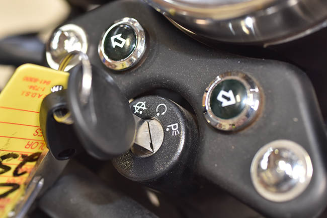
| The ignition switch is located on top of the forks. |
 |
|
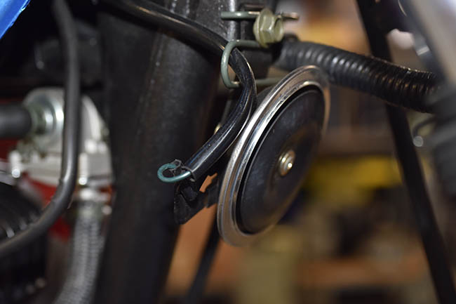
| The horn is located on the frame immediately behind the forks. It is accessible without removing the fuel tank. |
 |
|
| The fuel sensor sending unit is located beneath the fuel tank. | 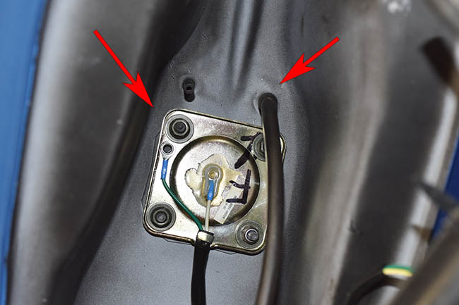 |
|
| The connector from the fuel tank’s fuel gage sending unit to the fuel gage is underneath the tank. | 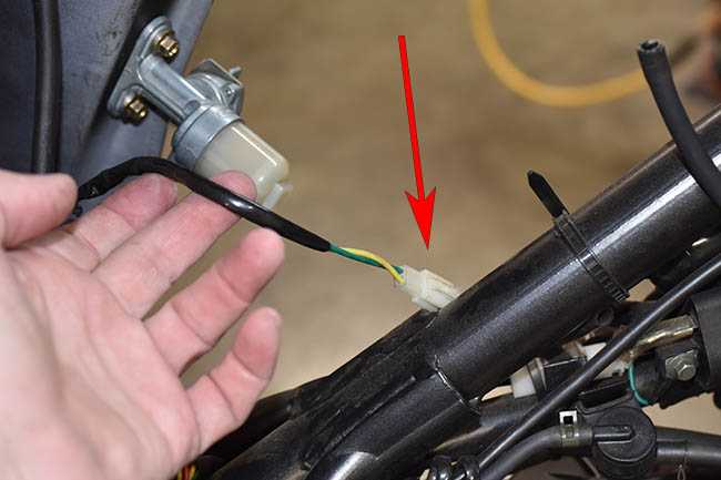 |
|
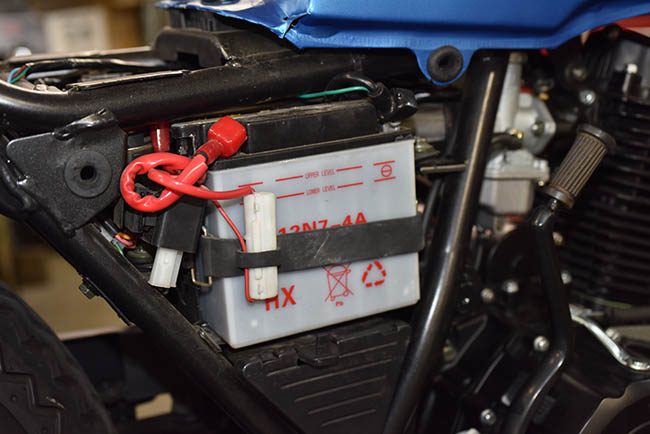
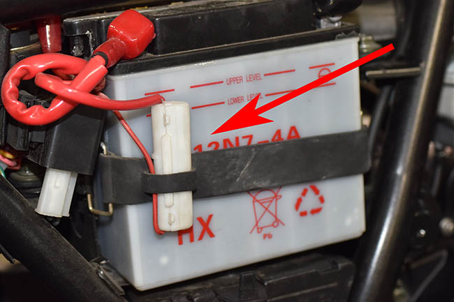
| The battery is located on the right side of the motorcycle. It is accessible by removing the right body panel. It is secured by a rubber strap. |
 |
|
| As you can see from the photo, red is positive, and green is ground. Throughout the motorcycle, wires with green insulation are ground wires. |
|
|
| The rectifier and the CDI are underneath the fuel tank. If this component is not working, the battery will not charge properly or it may overcharge and boil over. | 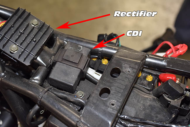 |
|
| The ignition coil is located underneath the fuel tank on the right side of the motorcycle frame. | 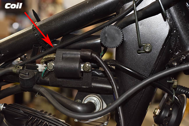 |
|
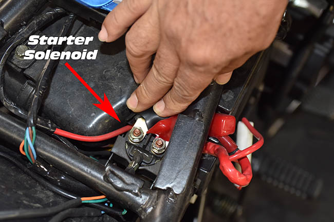
| The starter solenoid is located on the right side of the motorcycle just to the rear of the battery. It closes when commanded to do so to send power to the starter motor. |
 |
|
| The motorcycle’s only electrical fuse is located in a carrier alongside the battery. This pops open to provide access to the fuse. |
 |
|
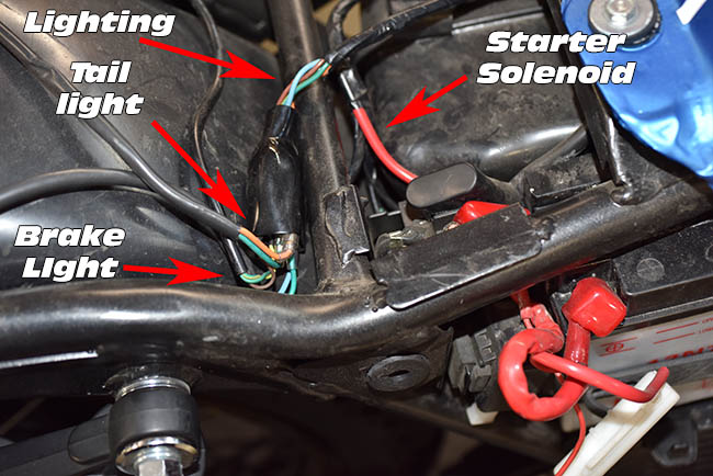
| If the motorcycle loses all electrical power, there are several potential causes, but the most likely are that the fuse has opened, or the engine kill switch is in the off position. Several of the connectors and harnesses under the seat are identified in this photo. |
 |
|
| Another connector bundle is located on the left side of the engine just above the transmission. | ||
| These are the connectors inside the shroud shown above. | ||
| The flasher and its connector are located immediately behind the battery. | 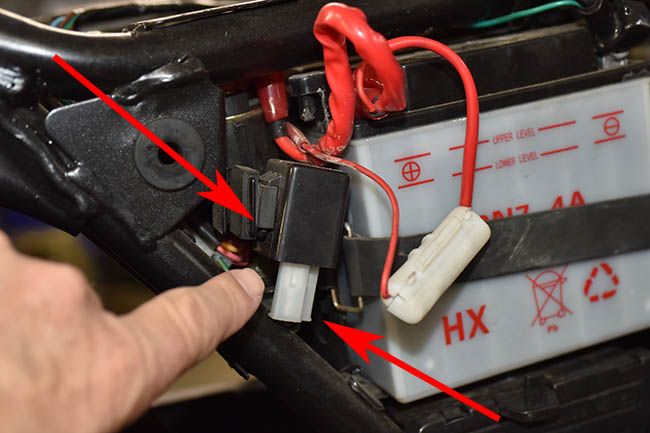 |
|
| The starter solenoid connector is located beneath the starter solenoid. | 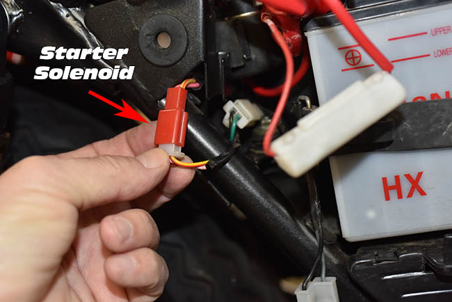 |
|
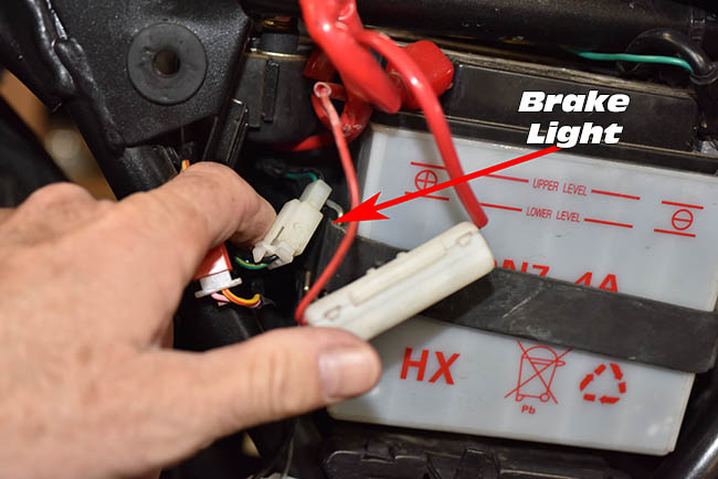
| The rear brake pedal brake light connector is located just behind the battery. |
 |
|
| Connectors and harnesses for the controls are located beneath the fuel tank. | 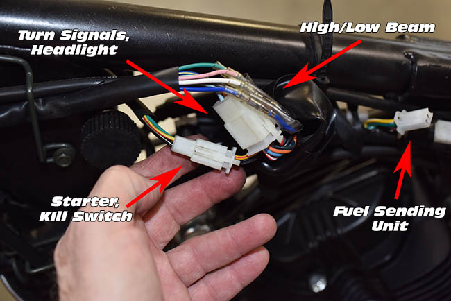 |
|
This SG250 Owner’s and Service Manual provides a wiring diagram, which can be used in conjunction with the above photos when troubleshooting any electrical problems.