RZ3 Valve Adjustment
RZ3 Valve Adjustment Tutorial
This tutorial addresses how to adjust the RZ3’s valves.
General Information
• The RZ3 has a high performance parallel-twin, single overhead cam, 8-valve engine. There are four exhaust valves and four intake valves. The engine’s single camshaft has four lobes that actuate four rocker arms. Two rocker arms actuate intake valves; the other rocker arms actuate exhaust valves. When the left cylinder of the engine is at the top of its compression stroke (at top dead center), the left valves are closed. When the right cylinder of the engine is at the top of its compression stroke (at top dead center), the right valves are closed.
• Thermal expansion occurs as engine temperature increases during normal operation. In order to compensate for this thermal expansion, there is a gap in the cam lobe/rocker arm/valve train (referred to as valve gap). As the engine warms, this gap approaches zero.
• As the valve impacts the valve seat repeatedly during normal operation, microscopic deformation occurs in both the valve and the valve seat. This deformation grows over time as the engine runs. As the deformation increases, it reduces the valve gap (i.e., the clearance built into the valve train to account for thermal expansion). Over time, the valve gradually moves higher into the cylinder head and the valve gap decreases. If the valve gap decreases beyond acceptable limits, it will result in the valve being held off the valve seat when the valve is supposed to be closed. This greatly reduces heat transfer from the valve to the cylinder head, the valve temperature increases, and the valve will be damaged. Valve gap that is inadequate also makes the engine harder to start. Valve gap adjustment keeps the valve gap within acceptable limits.
• The RZ3 engine uses a threaded adjustor shaft with a lock nut to set and lock the valve gap. These adjustors are located in the ends of the rocker arms that interface directly with the valve stem.
• The RZ3 valve adjustment procedure consists of several actions, including gaining access to the valve rocker arms and their adjustment screws, rotating the engine to top dead center such that the valves are closed, loosening the threaded adjustor lock nuts, setting the valve gaps to the specified gap, tightening the lock nuts to lock the threaded adjustors at this gap, and then reassembling the motorcycle.
• Most of the work in adjusting the valves is associated with gaining access to the adjustors. The adjustment operation (once the valve train is accessed) takes only a few minutes.
• Valve adjustment requires a cold engine. Allow your motorcycle to cool completely before adjusting the valves.
• The valve gap should be set at 0.06mm for the intake valves, and 0.08mm for the exhaust valves.
• Tools required for adjusting the valves include feeler gages, an 8mm socket, an 8mm wrench, a 12mm wrench, a 15mm wrench, a 5mm Allen wrench, a 6mm Allen wrench, a 13mm deep socket, a 14mm deep socket, a 12mm socket, a 17mm socket, a 19mm socket, a flathead screwdriver, and a flashlight.
Procedure
Allow the motorcycle to cool completely such that the engine is at room temperature.
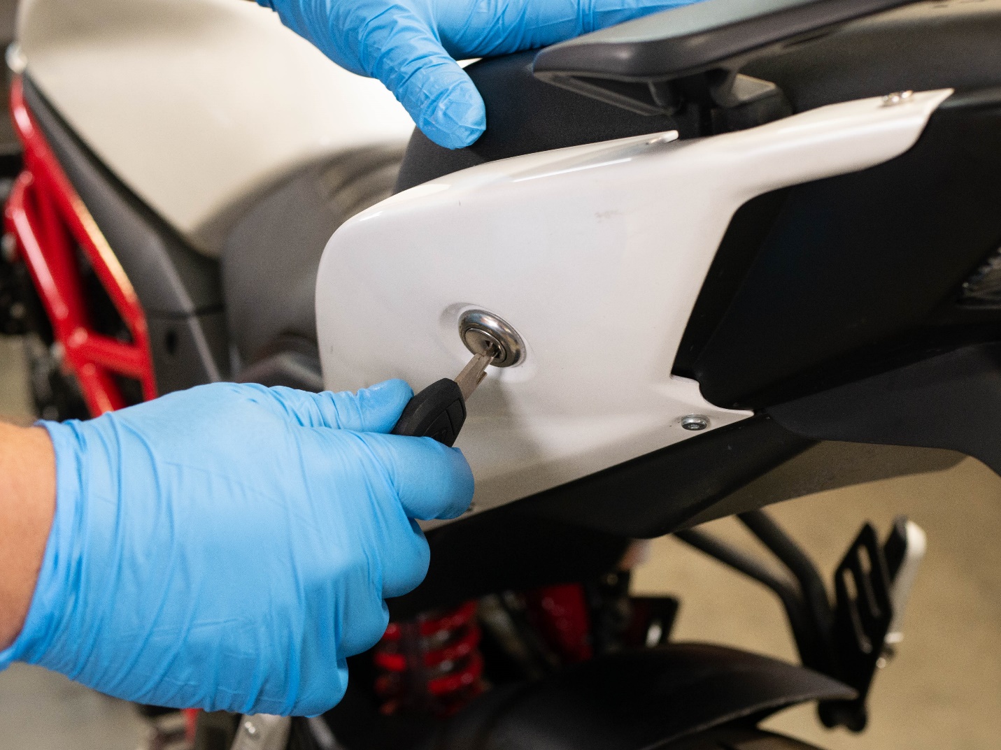
Insert the ignition key in the left side panel and remove the rear seat.
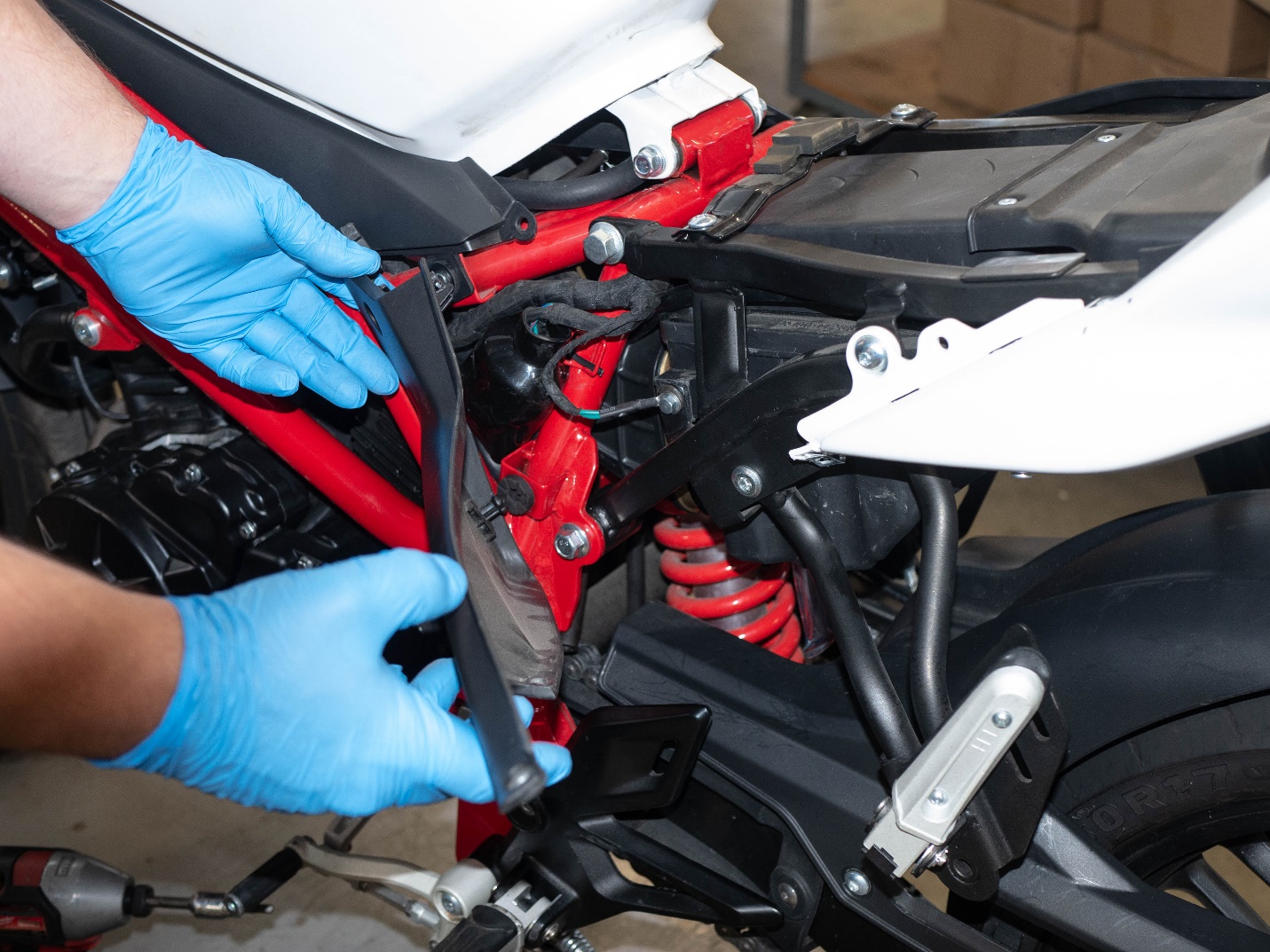
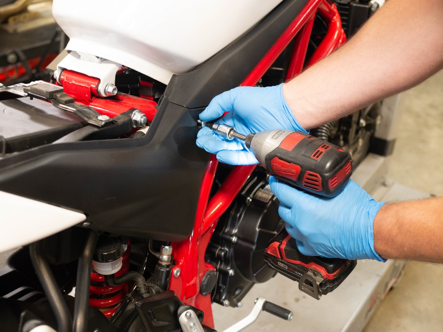
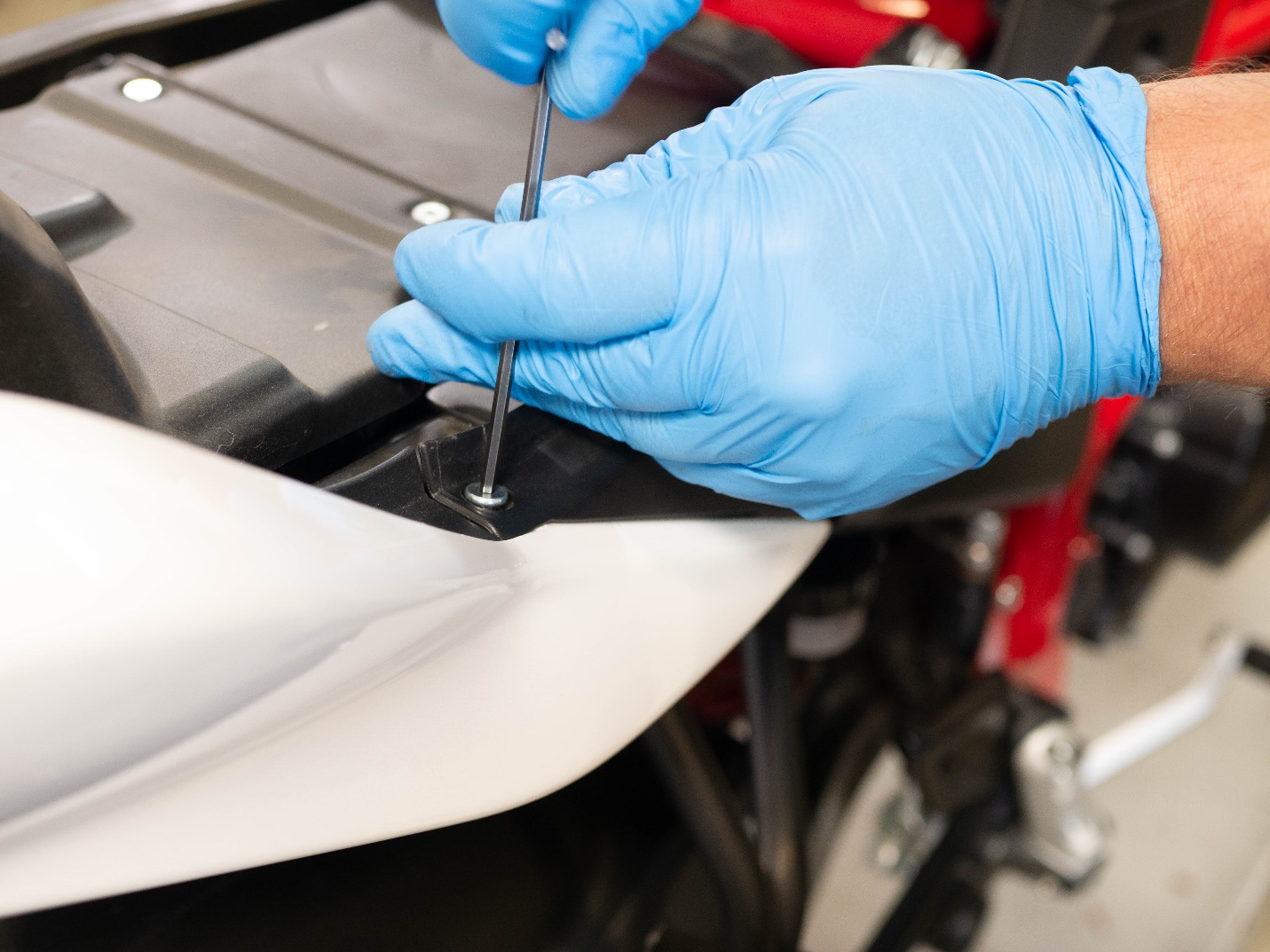
Remove the left and right side panels with a 3mm and a 5mm Allen wrench.
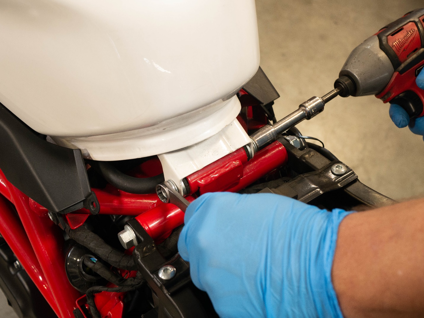
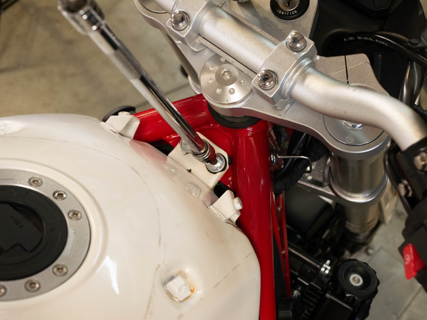
Remove the bottom fuel tank mounting hardware with a 12mm socket and a 12mm wrench.
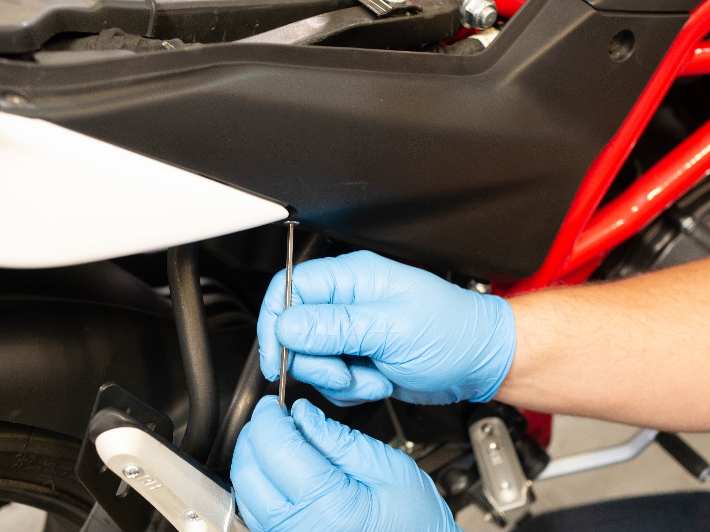
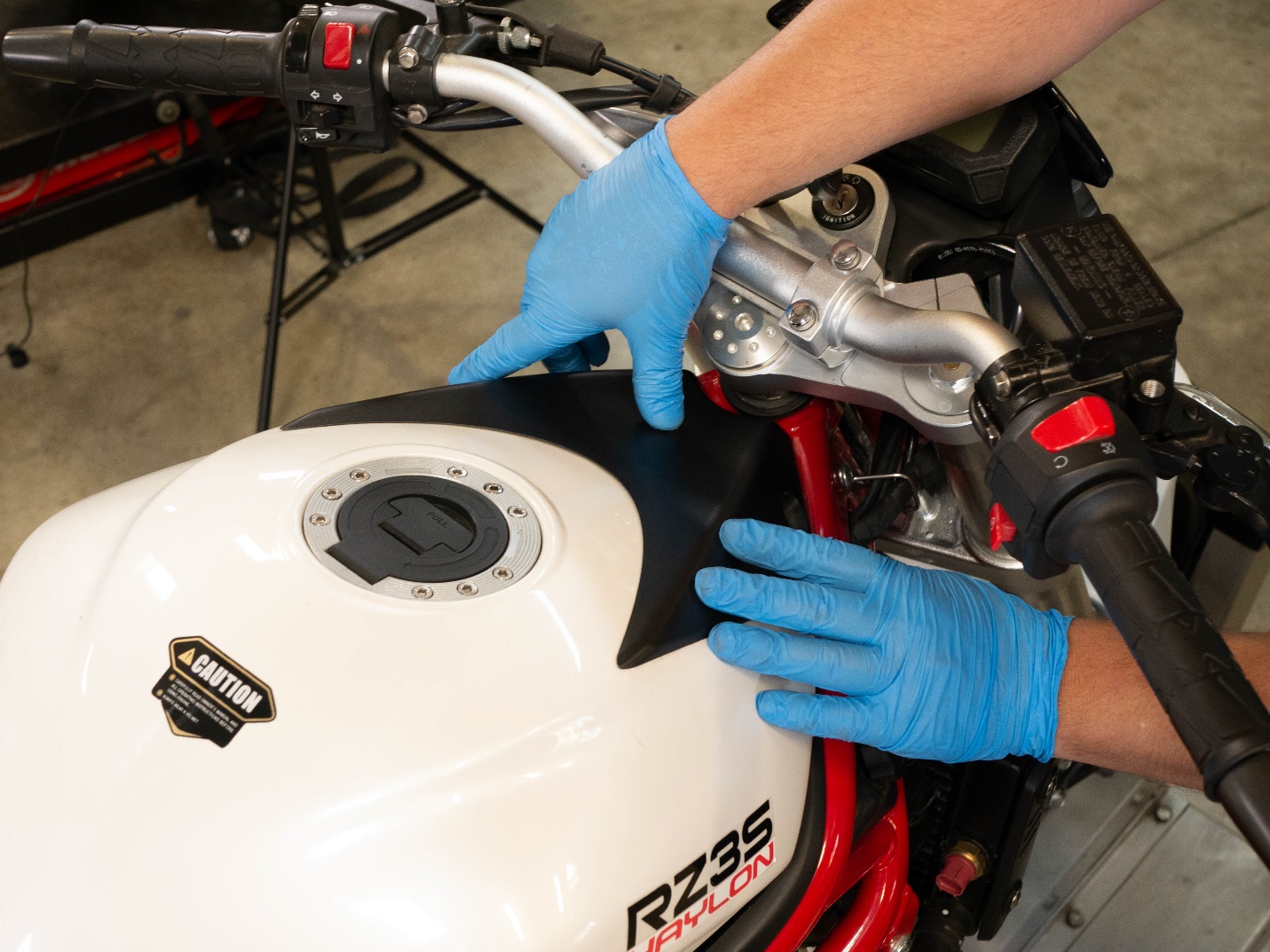
Remove the upper left and right tank panel hardware with a 5mm Allen wrench.
Push the tank panel towards the rear of the motorcycle and remove it.
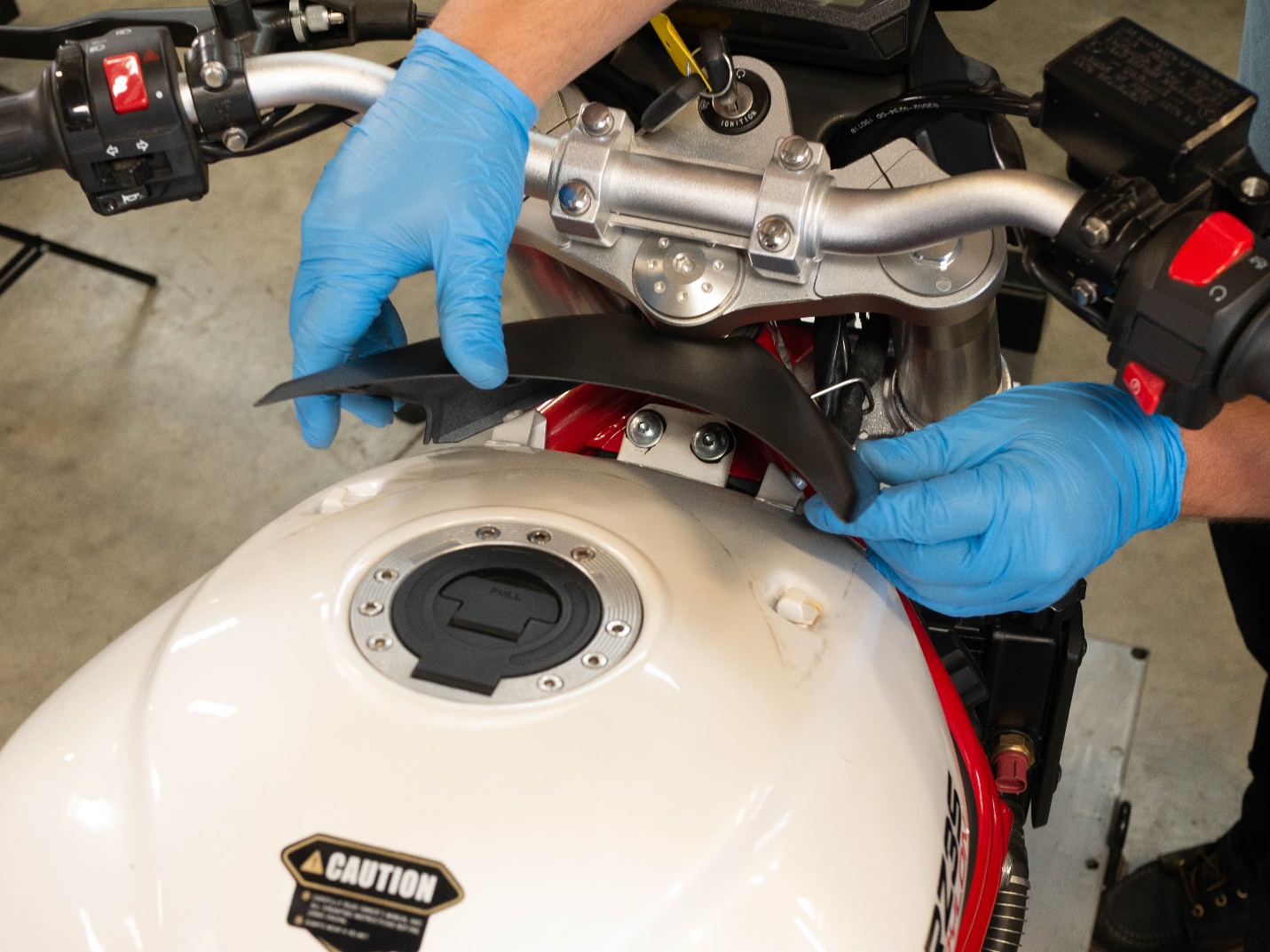
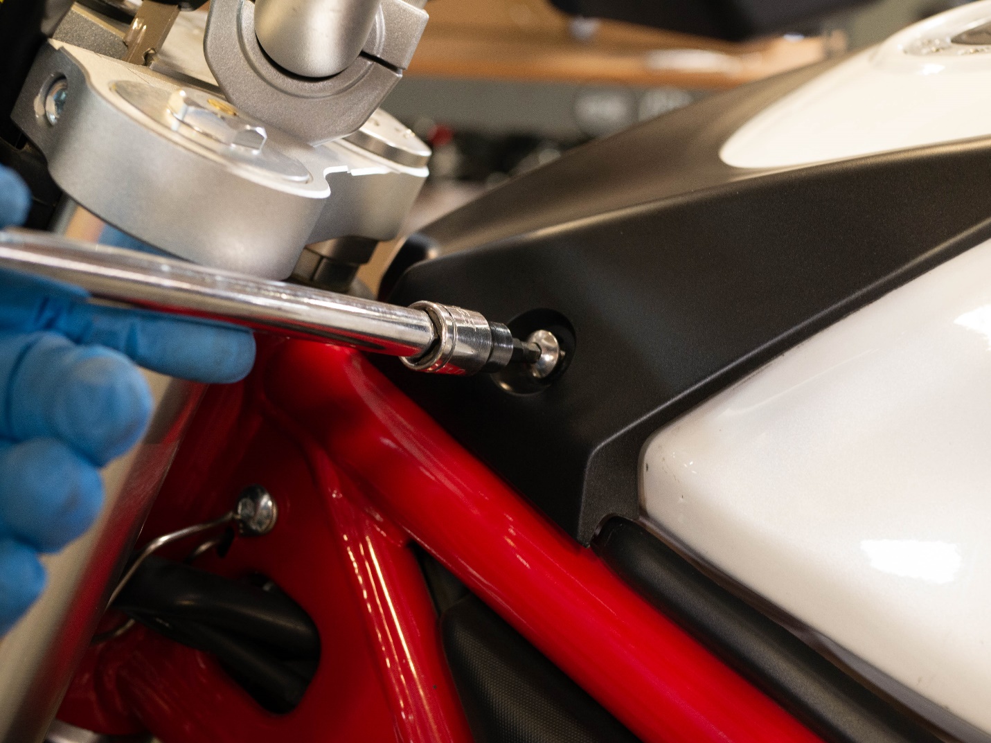
Remove the upper tank screws with a 5mm Allen wrench.
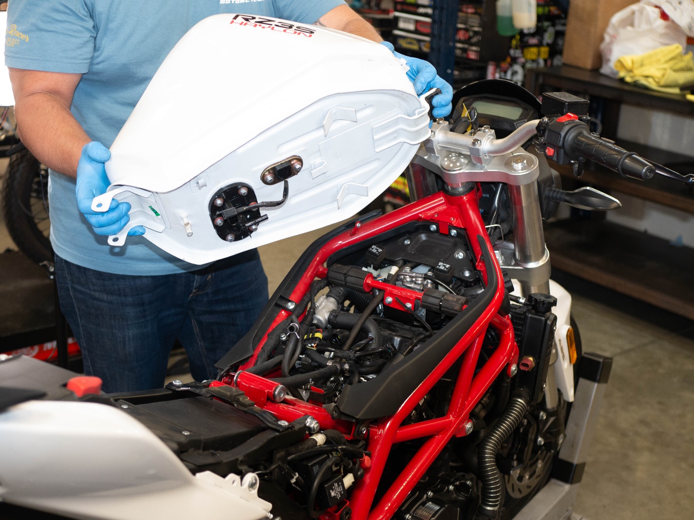
Lift the fuel tank upward.
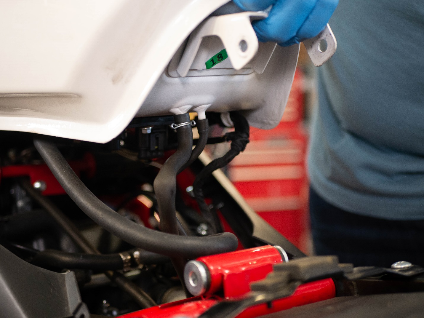
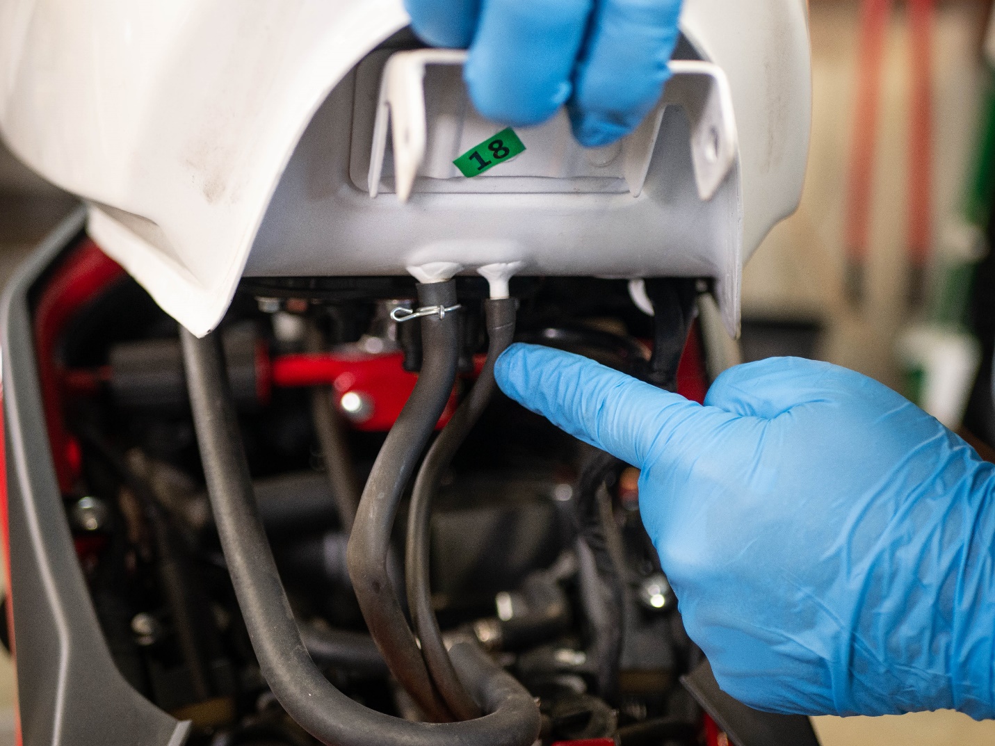
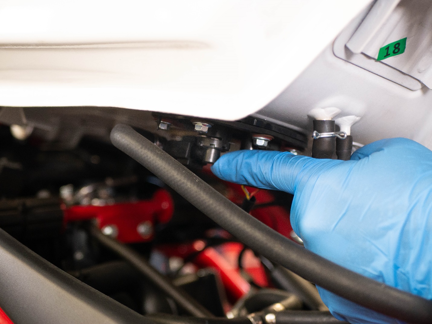
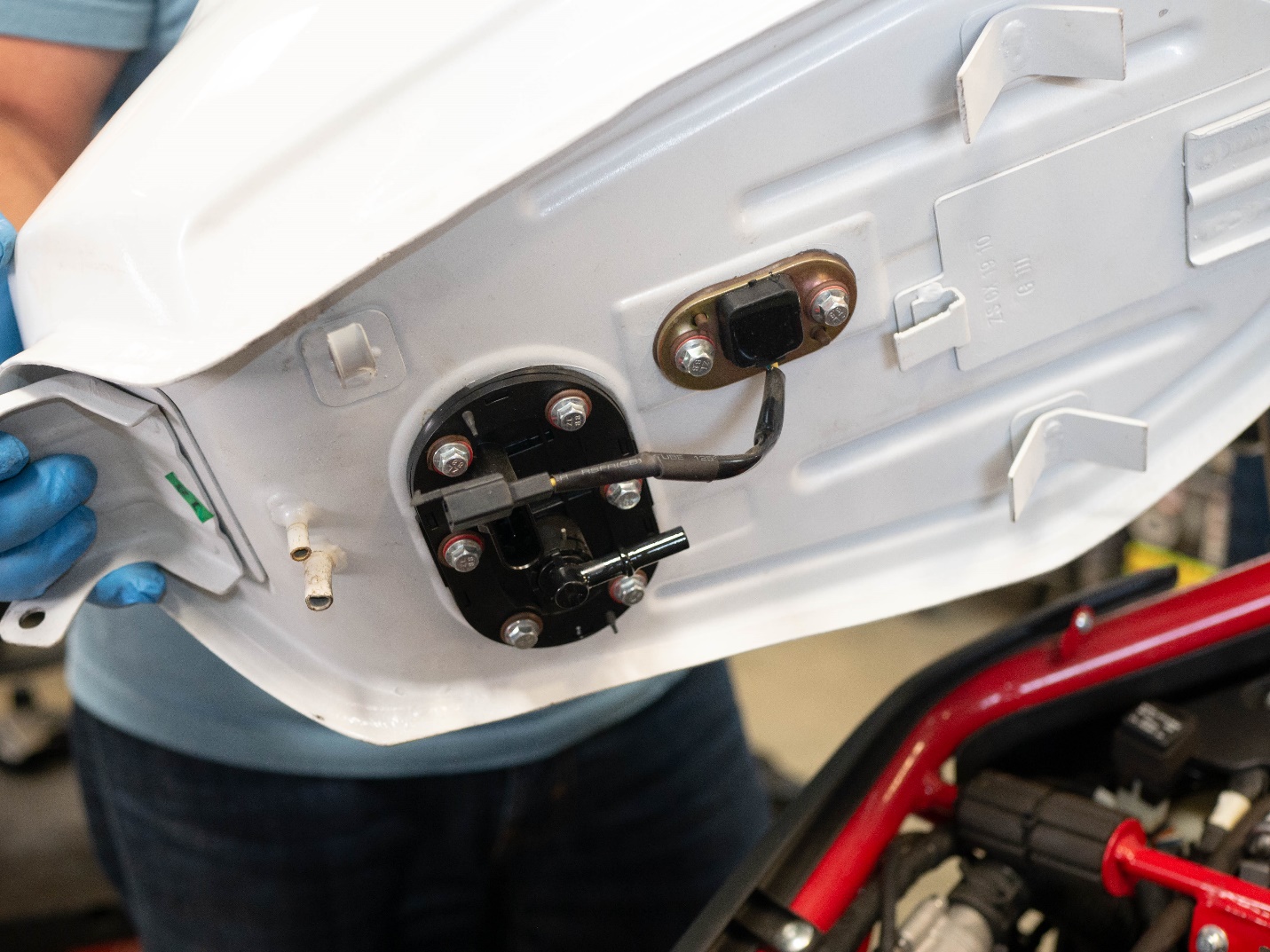
Disconnect the vent hose and overflow hose from under the tank.
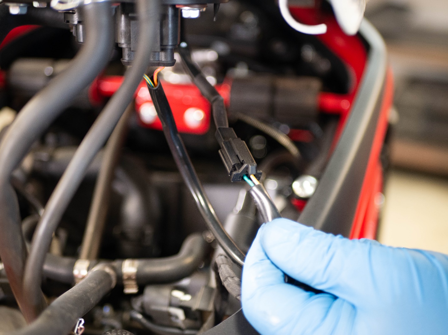
Use a flathead screwdriver to GENTLY release the tab and disconnect the fuel pump electrical connector.
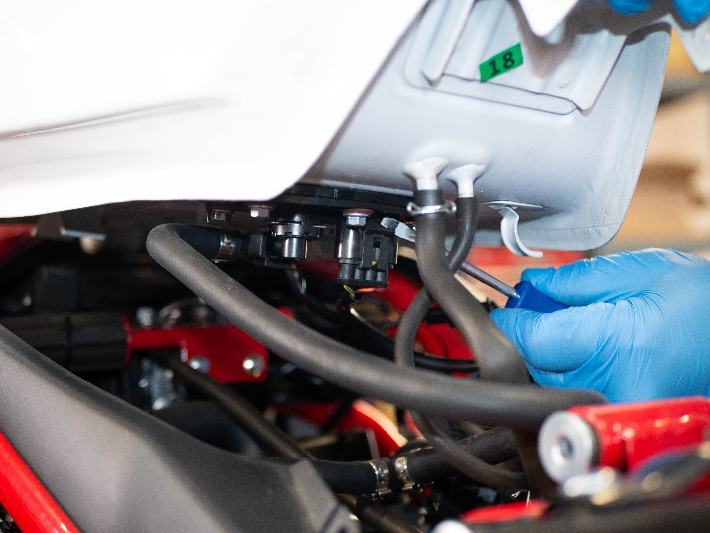
Disconnect the electrical connector from the fuel gauge sensor.
Pinch the plastic connector to remove the fuel supply line from the tank.
Remove the fuel tank from the motorcycle.
Remove spark plug caps.
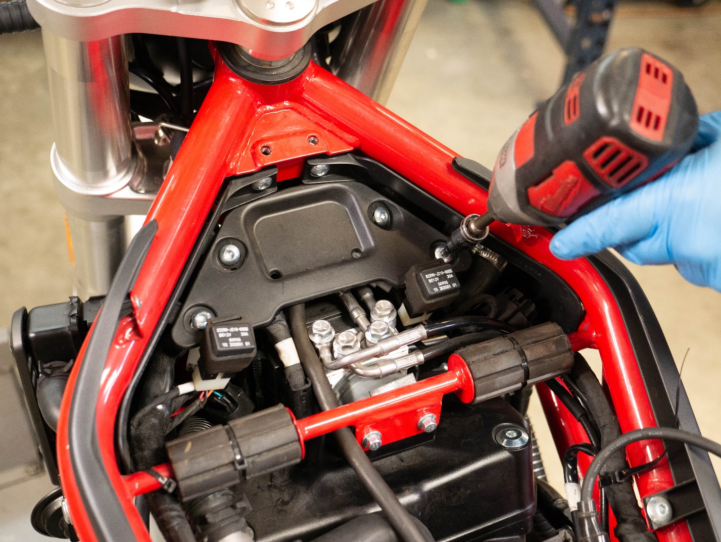
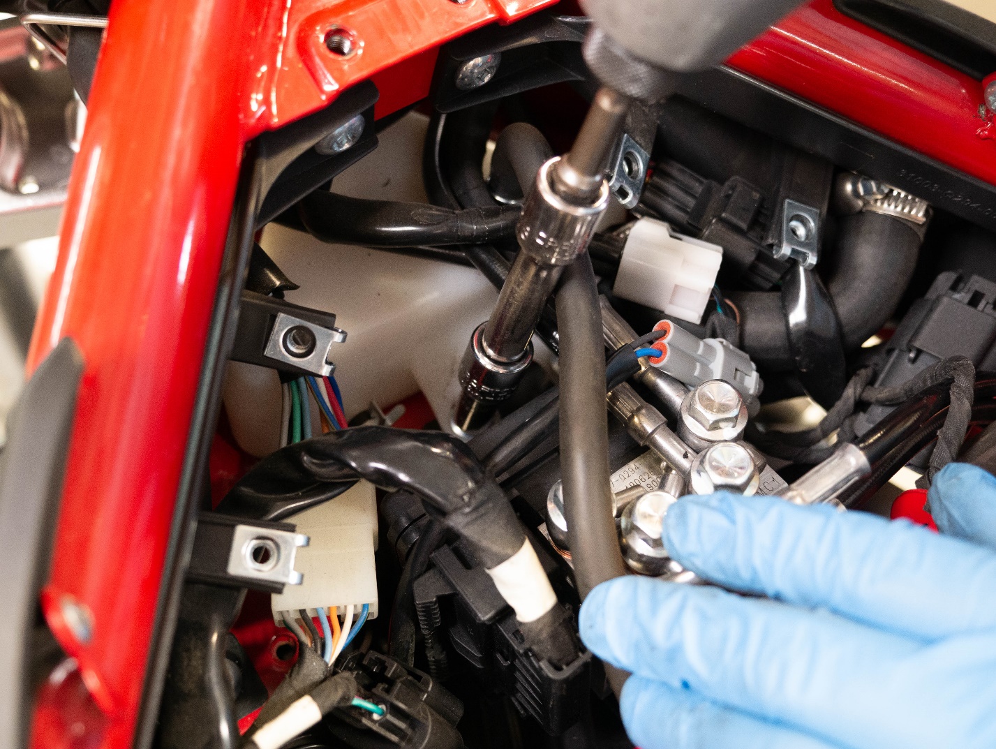
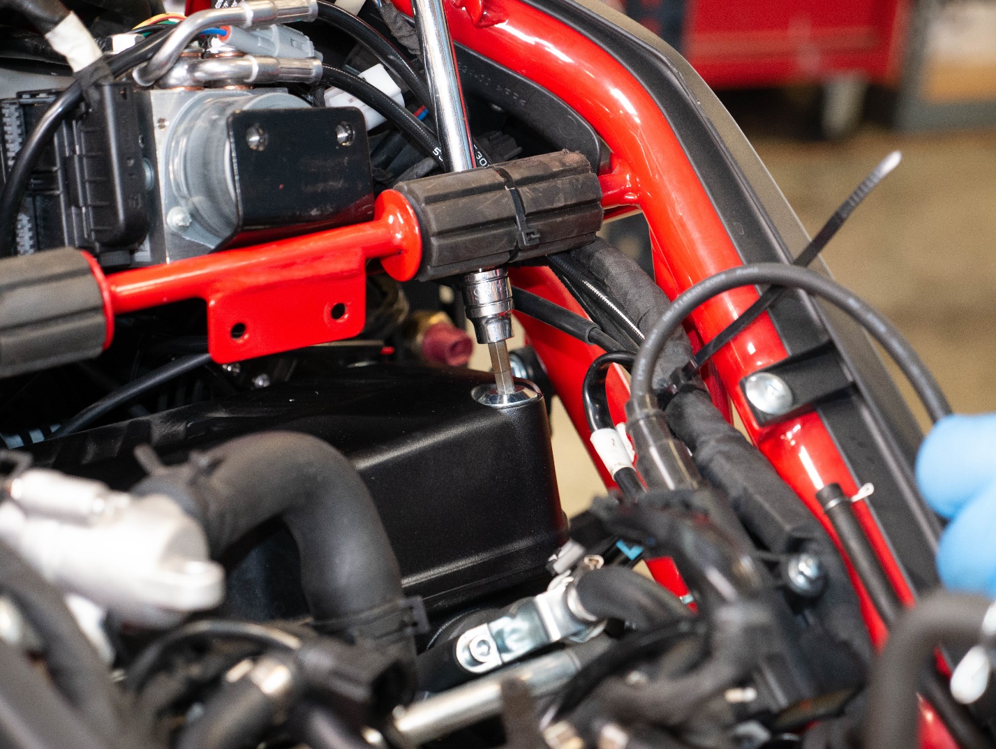
Remove the ignition coils using an 8mm socket.
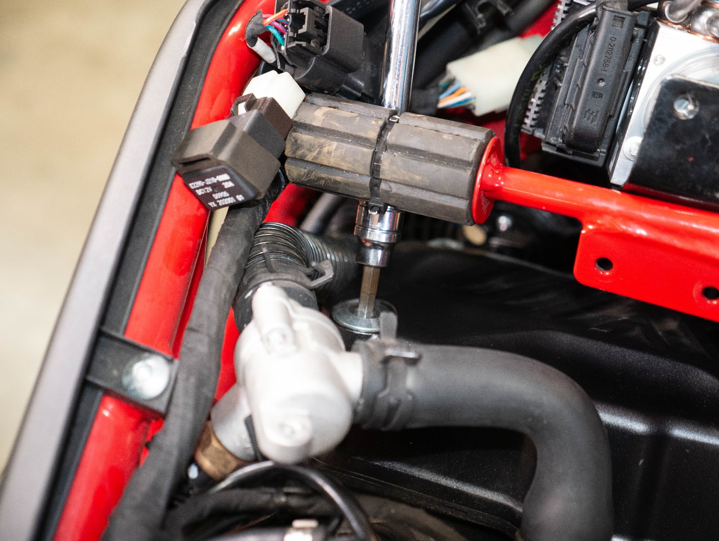
Remove the hose mount using an 8mm socket.
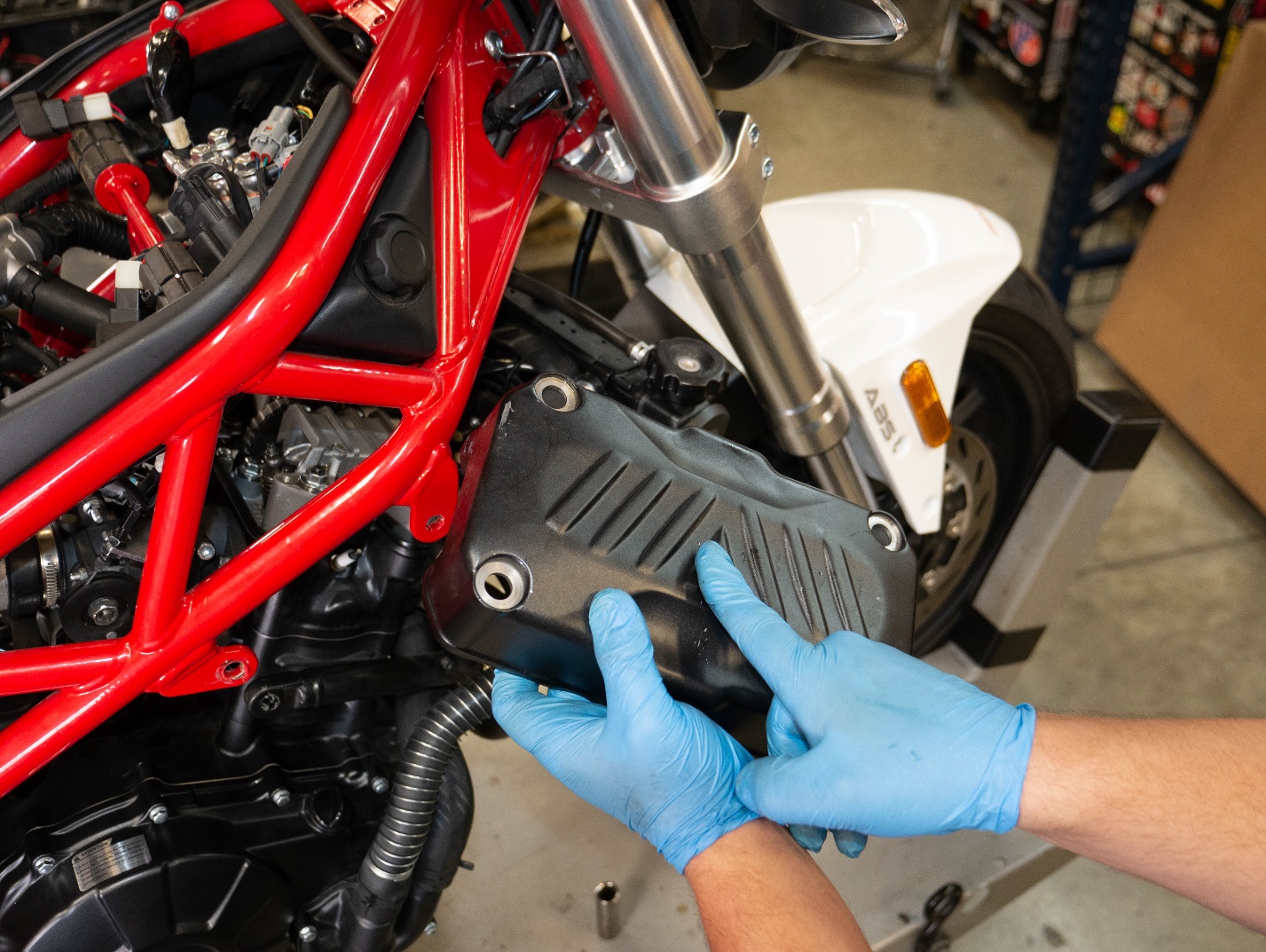
Remove the plastic cover using a 5mm Allen.
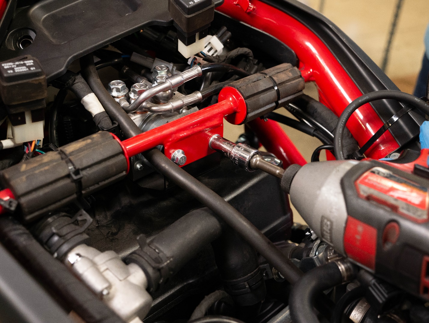
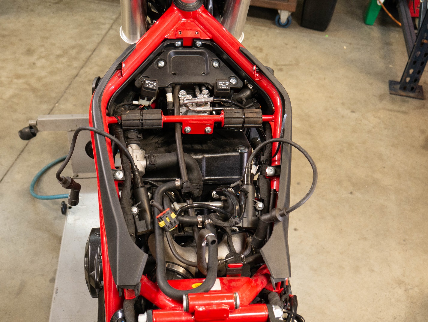
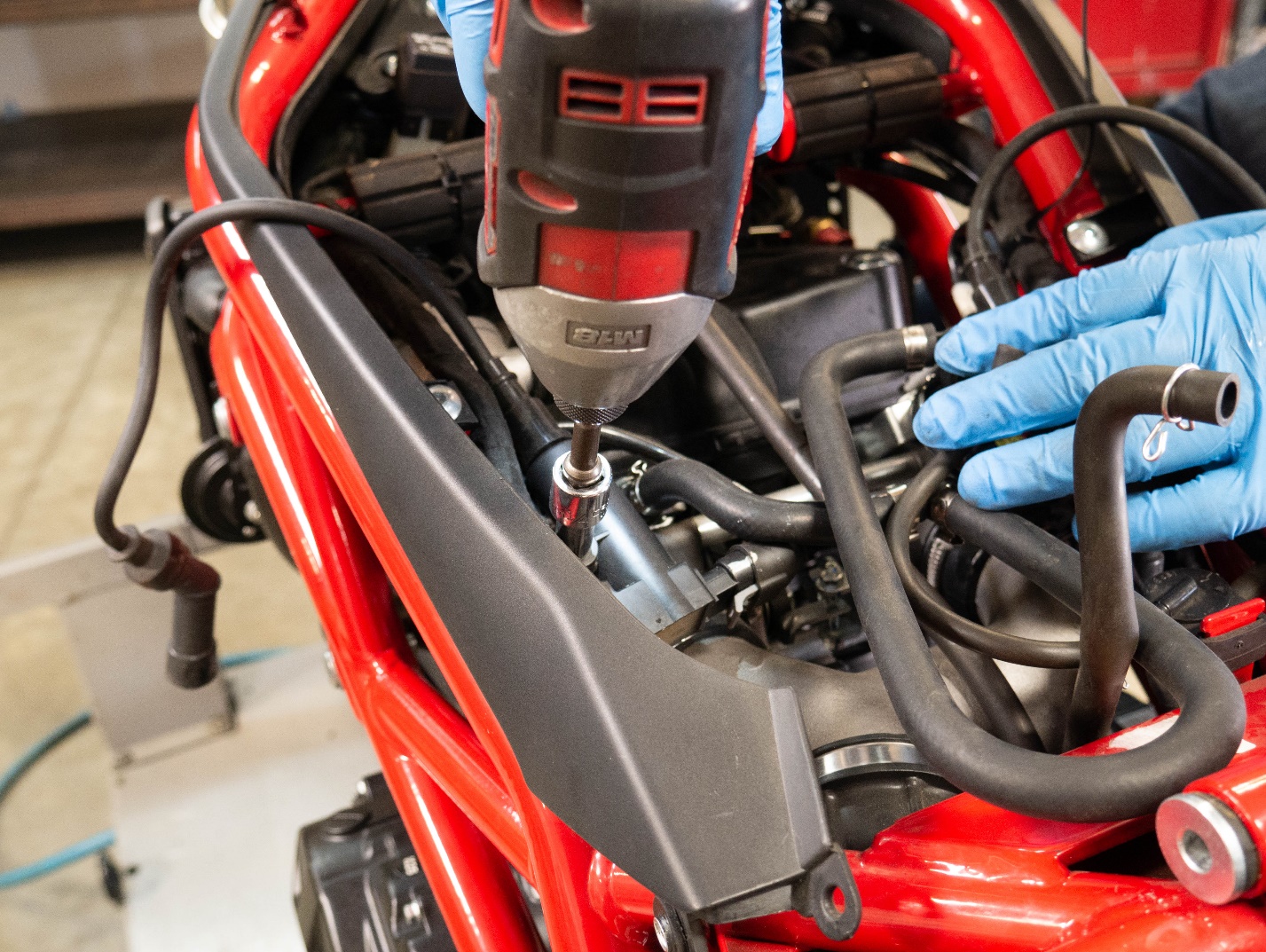
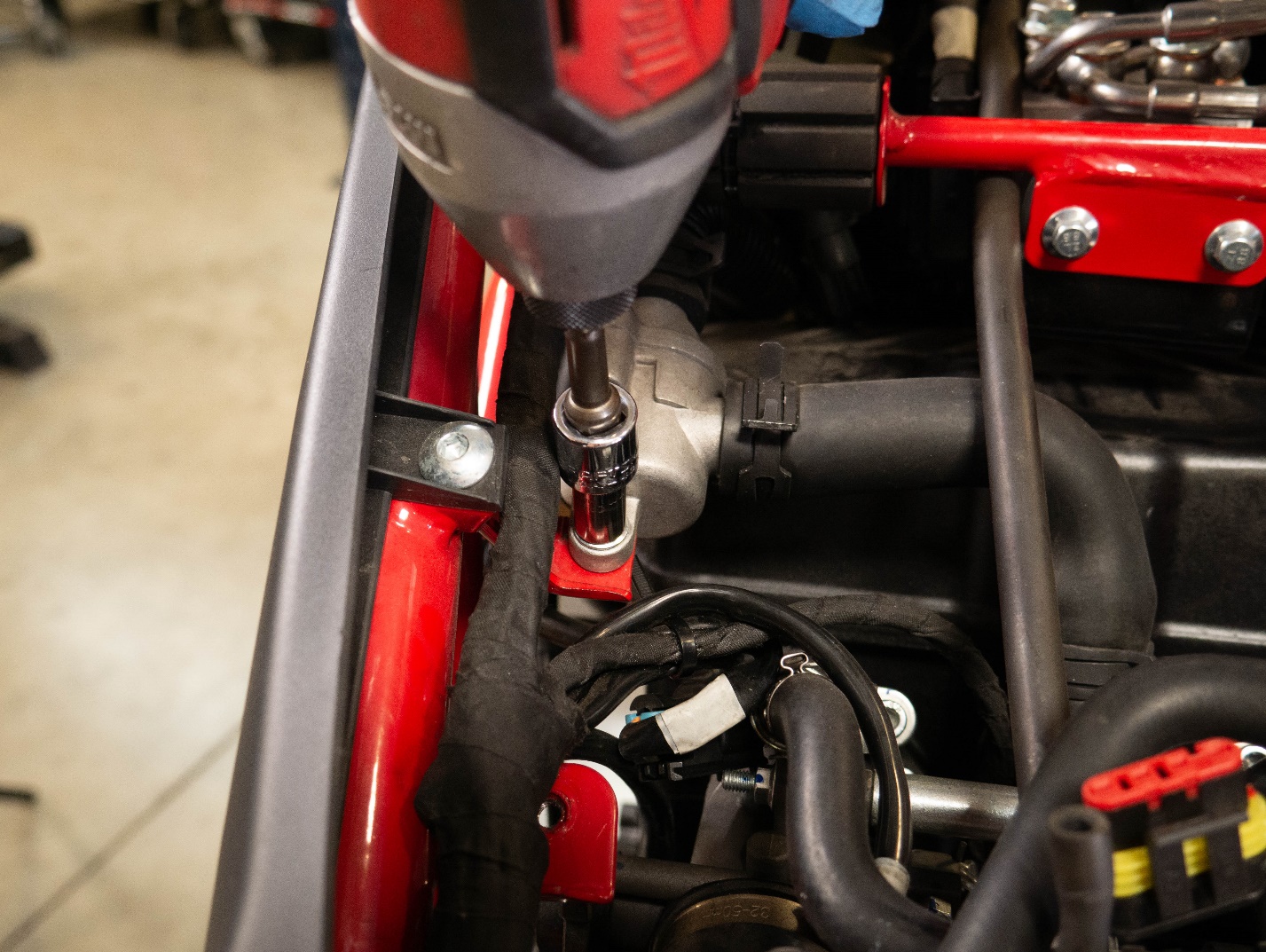
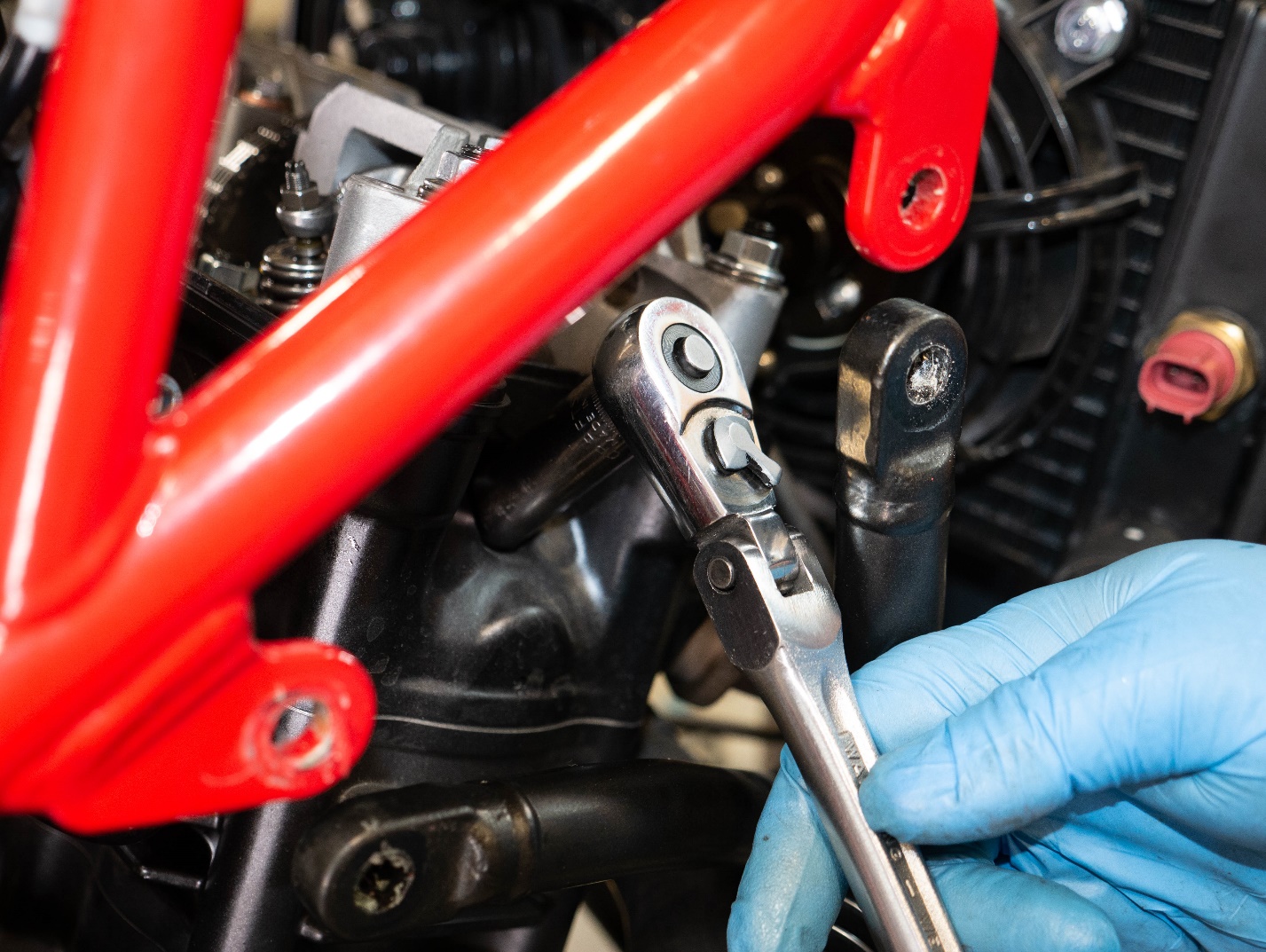
Remove the ABS block mount using an 8mm socket.
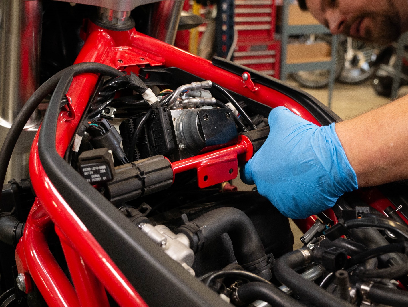
Pull the ABS block up and set it on the cross bar.
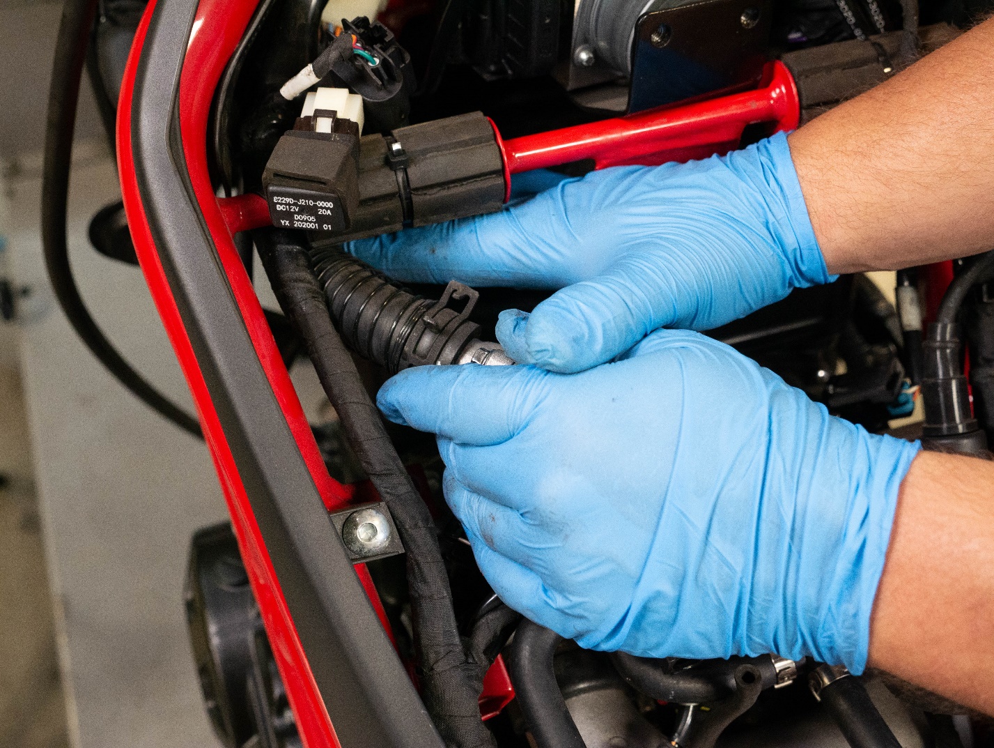
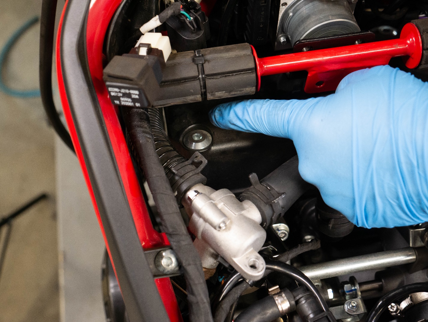
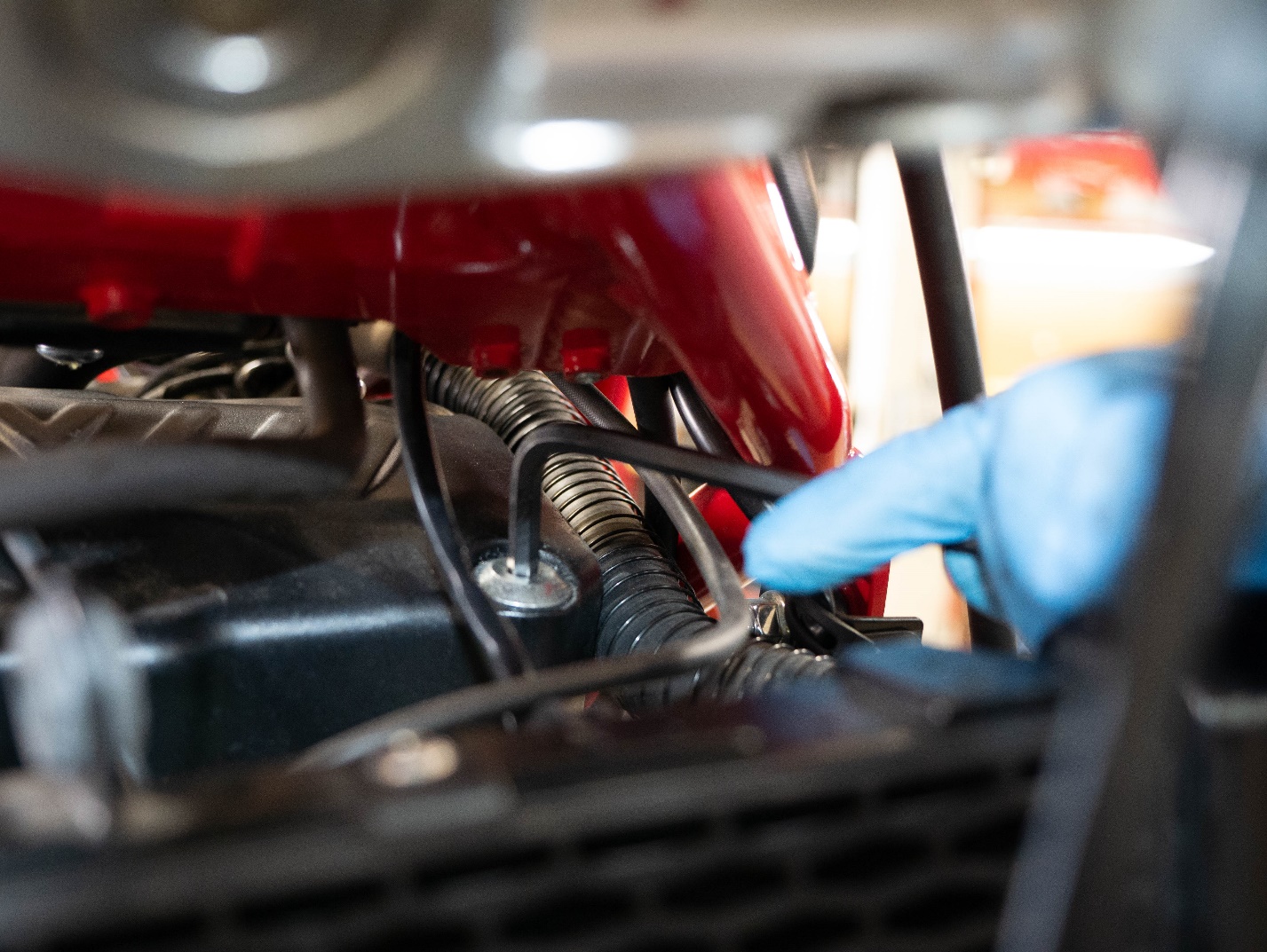
Gently and firmly push the coolant hose out of the way.
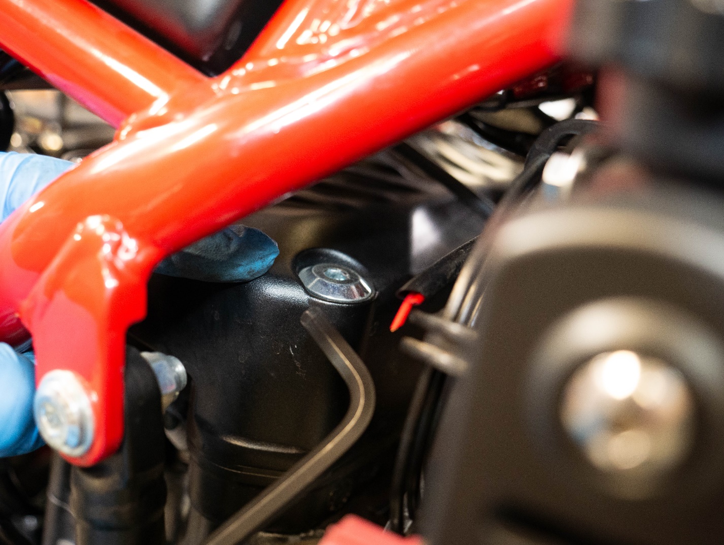
Remove the valve cover screws using a 5mm Allen.
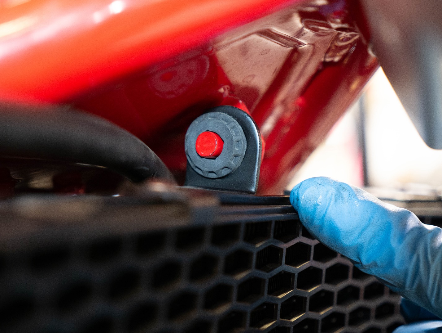
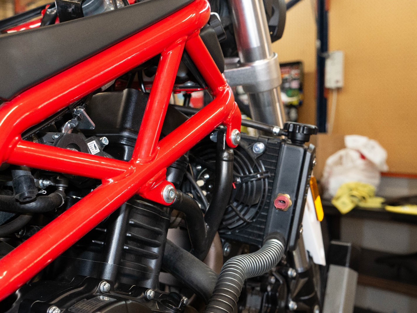
Slide the radiator away from the mounting peg for better access to the valve cover.
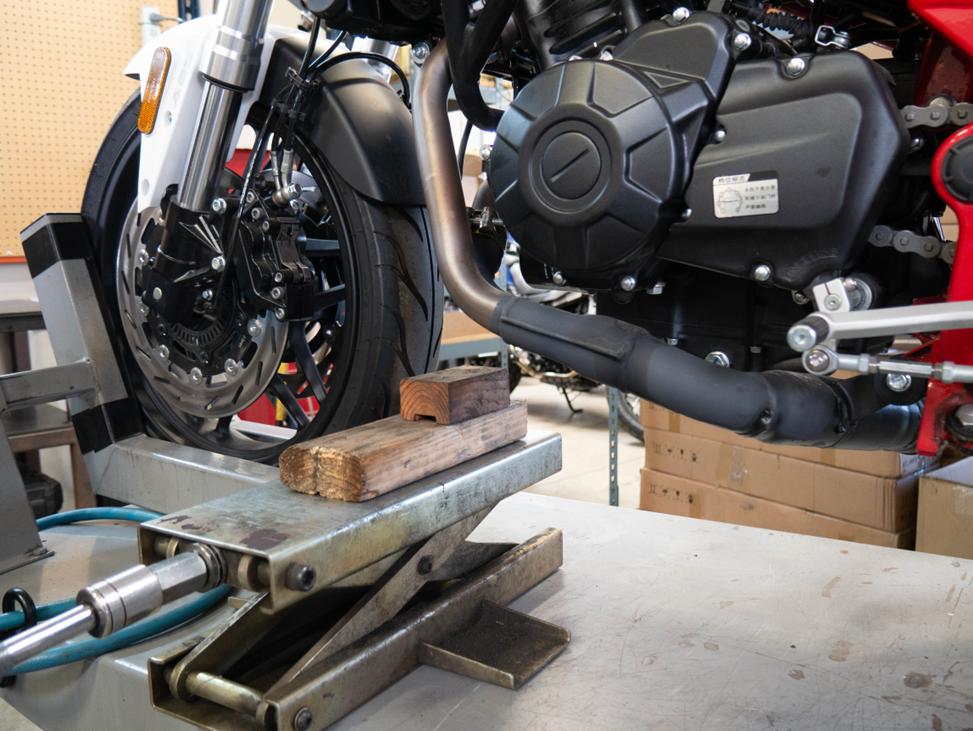
Place a jack under the engine. Use wooden blocks as spacers.
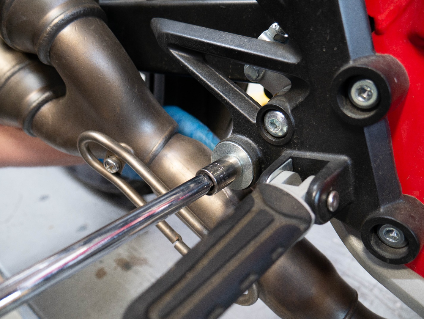
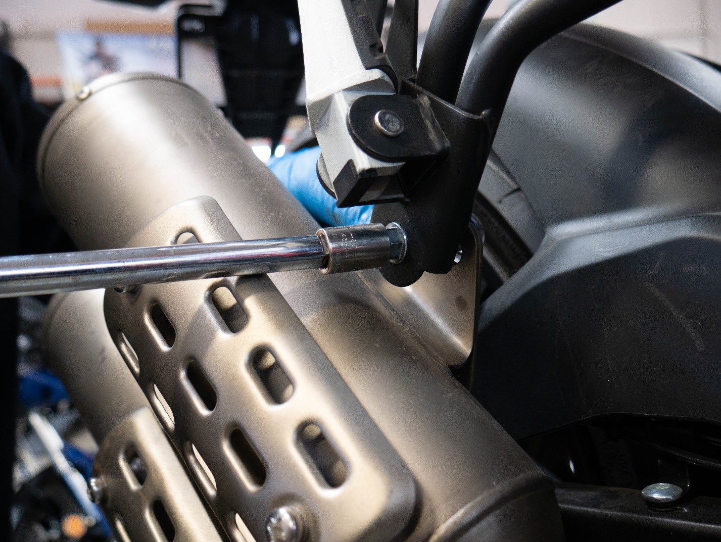
 Remove the exhaust mounting bolts using a 12mm socket and a 12mm wrench.
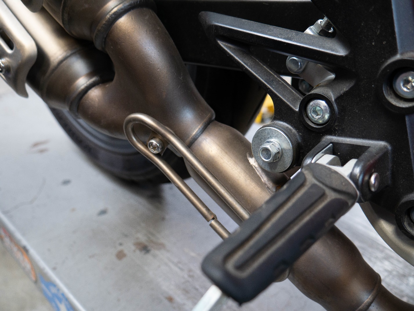
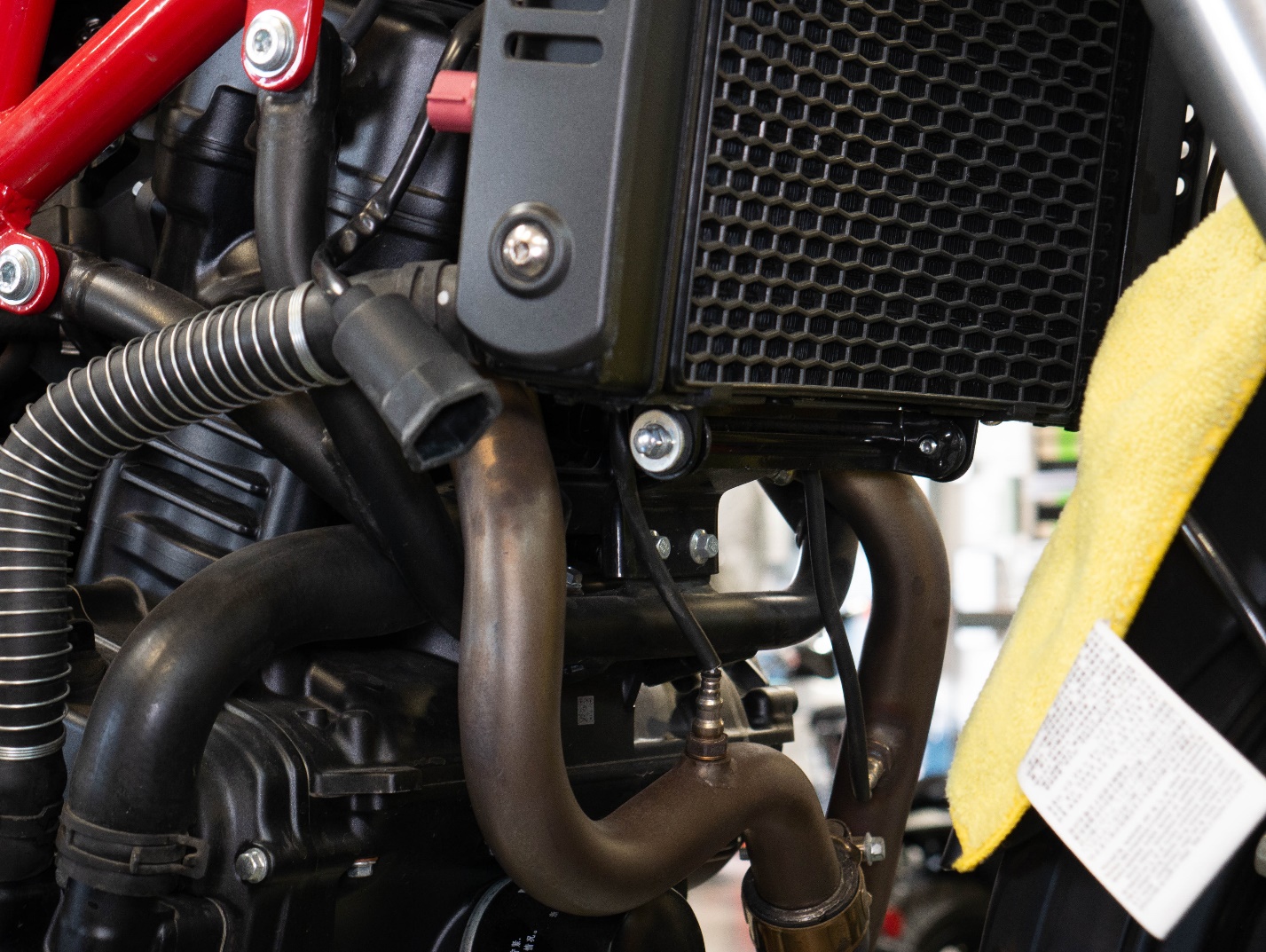
Remove the radiator mounts using an 8mm socket.
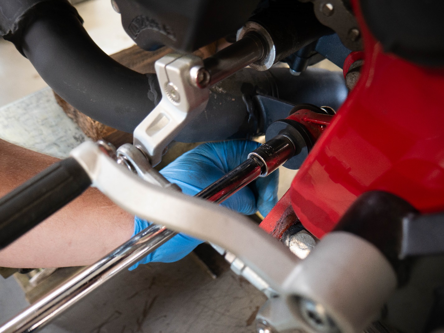
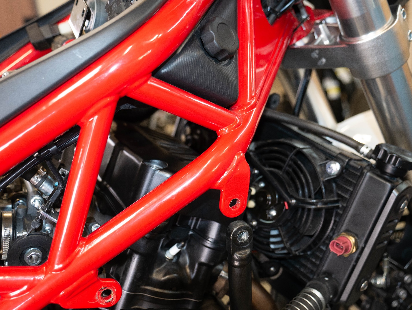
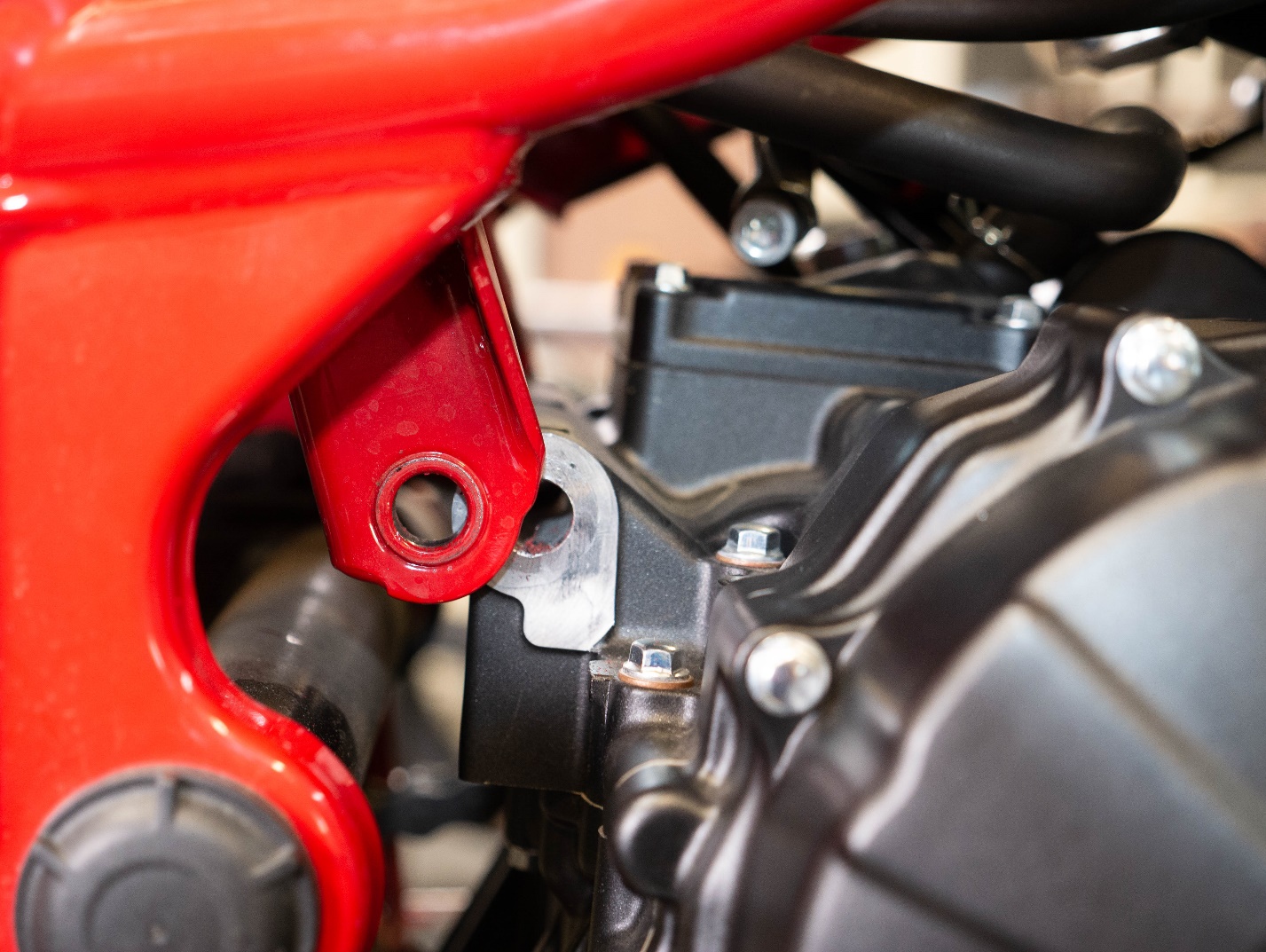
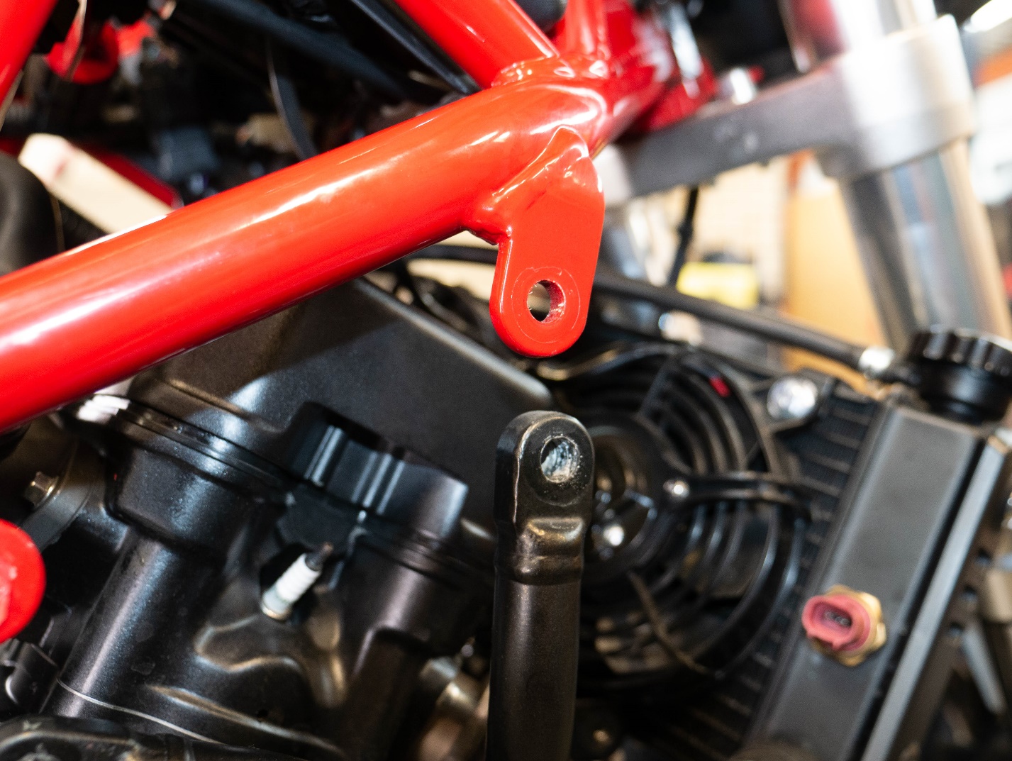
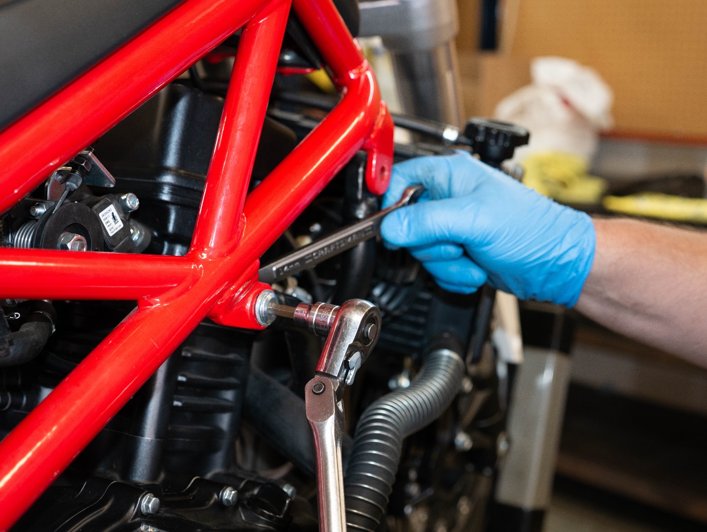 Remove the side engine mount bolts using a 6mm Allen and a 14mm wrench.
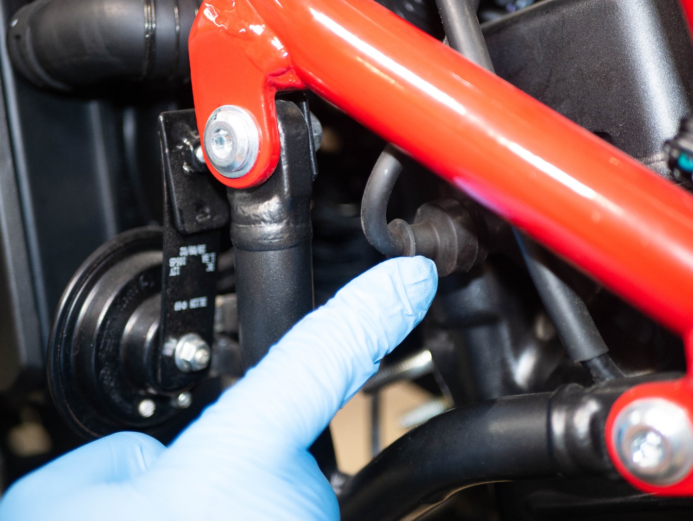
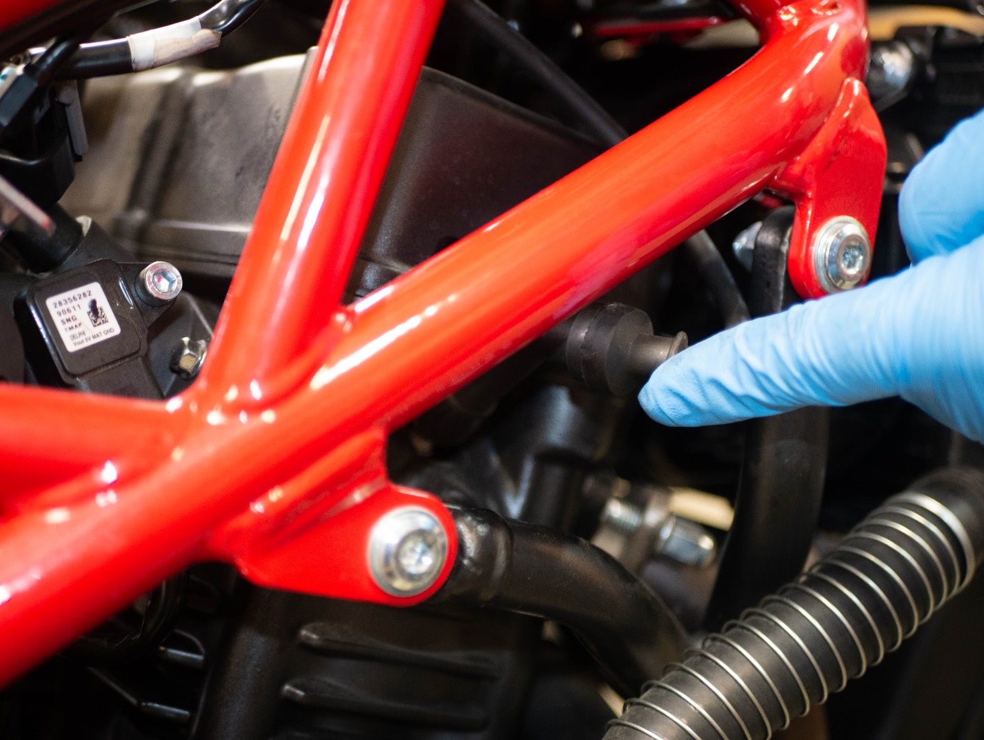
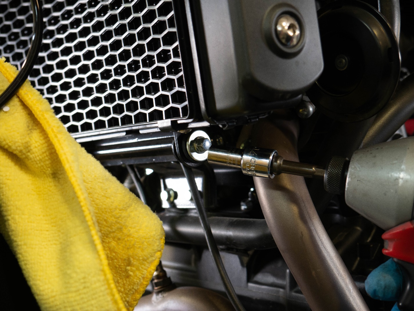
 Remove the rear engine mount bolt using a 17mm socket and a 15mm wrench.
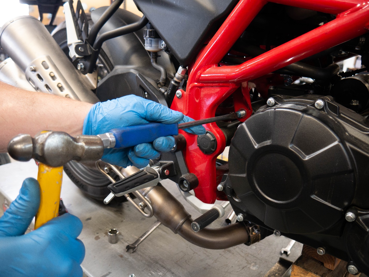
A hammer and punch may be needed to push out the rear engine mount bolt.
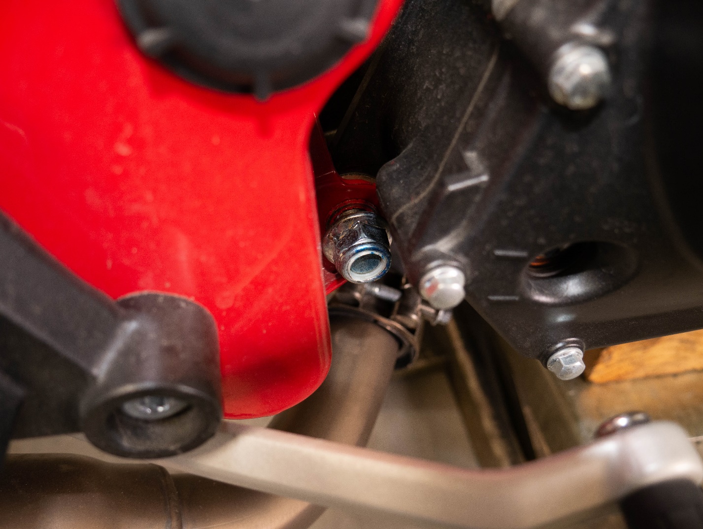
Loosen the lower rear engine mount bolt to allow the engine to pivot as it is lowered.
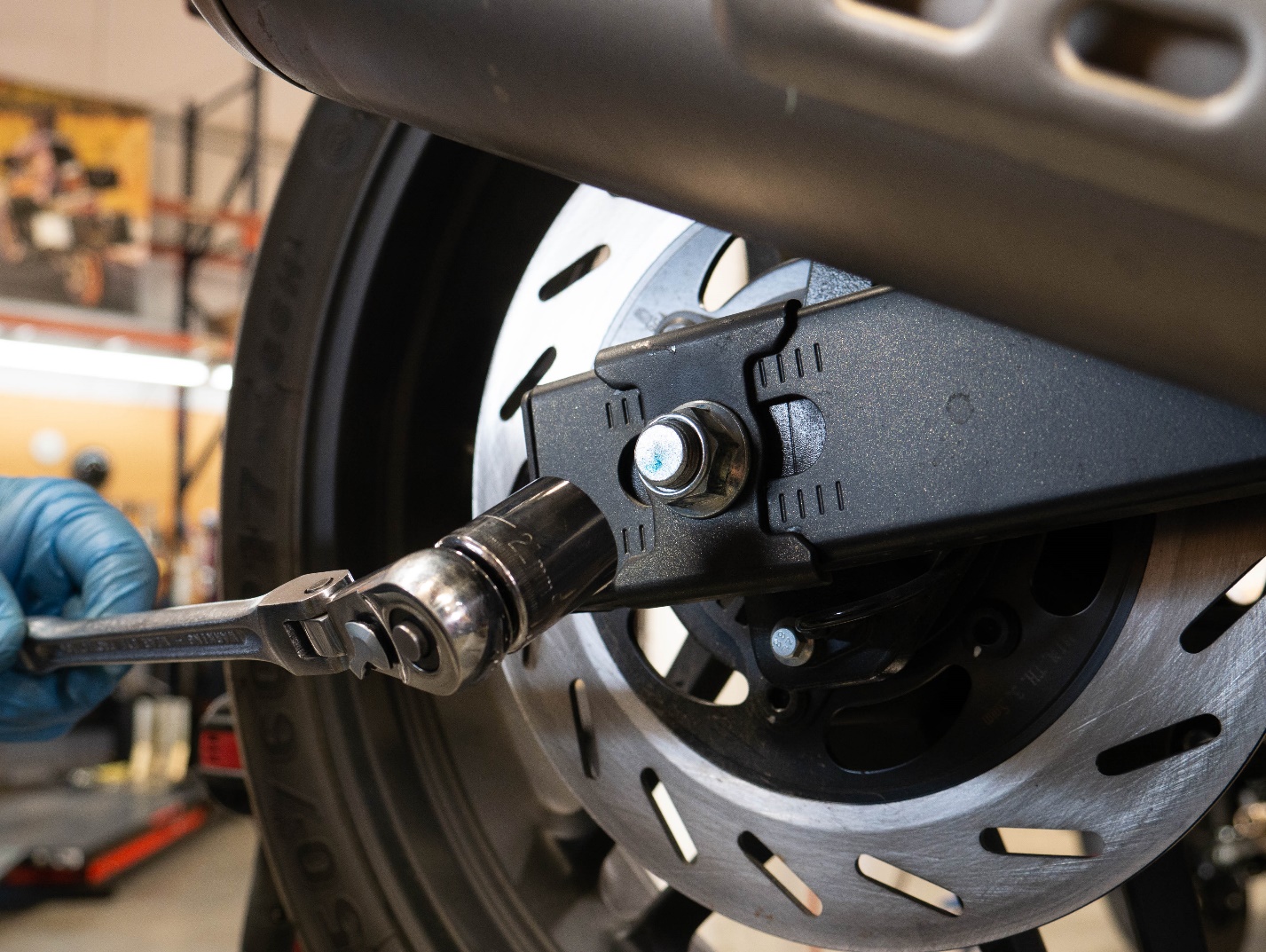
Loosen the axle nut using a 21mm socket.
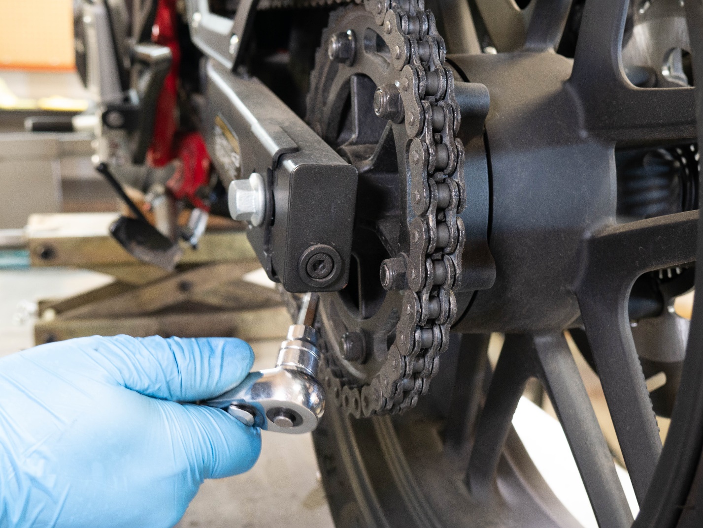
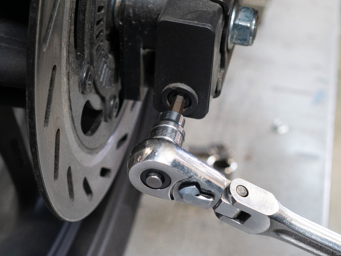
Loosen the chain using a 6mm Allen.
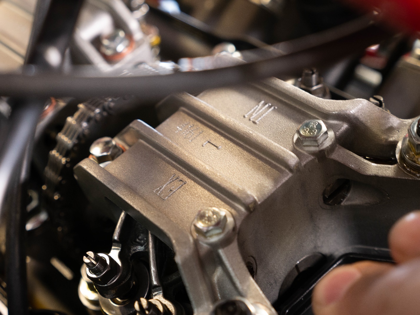
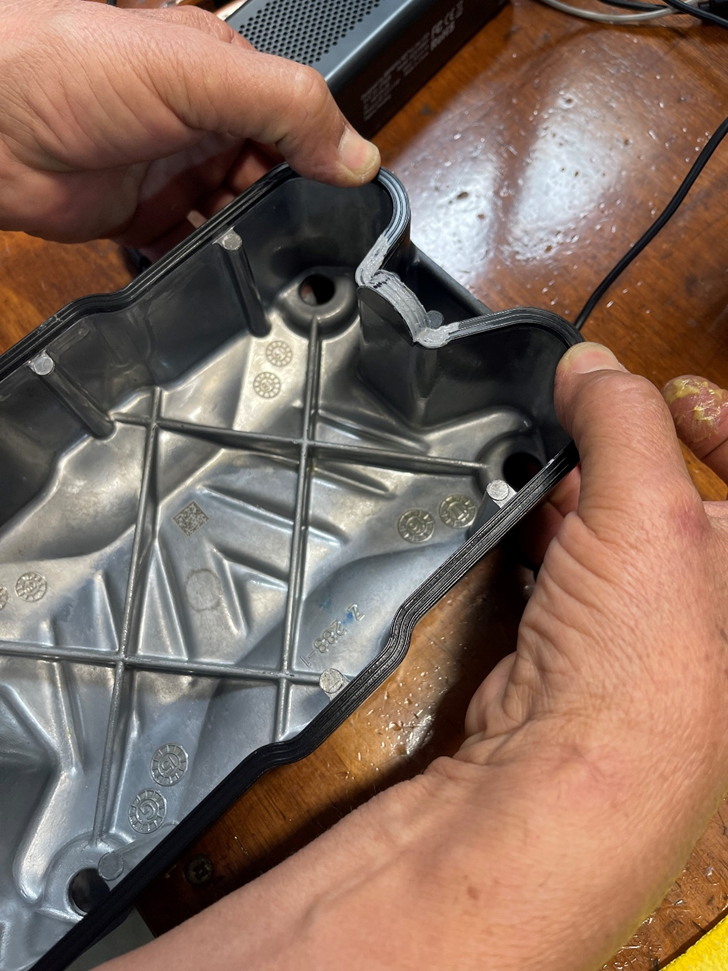
Use the jack to lower the engine and remove the valve cover. *Note the direction of the “arrow” stamping on the valve cover points forward.
Remove the spark plugs using a 13mm deep socket.
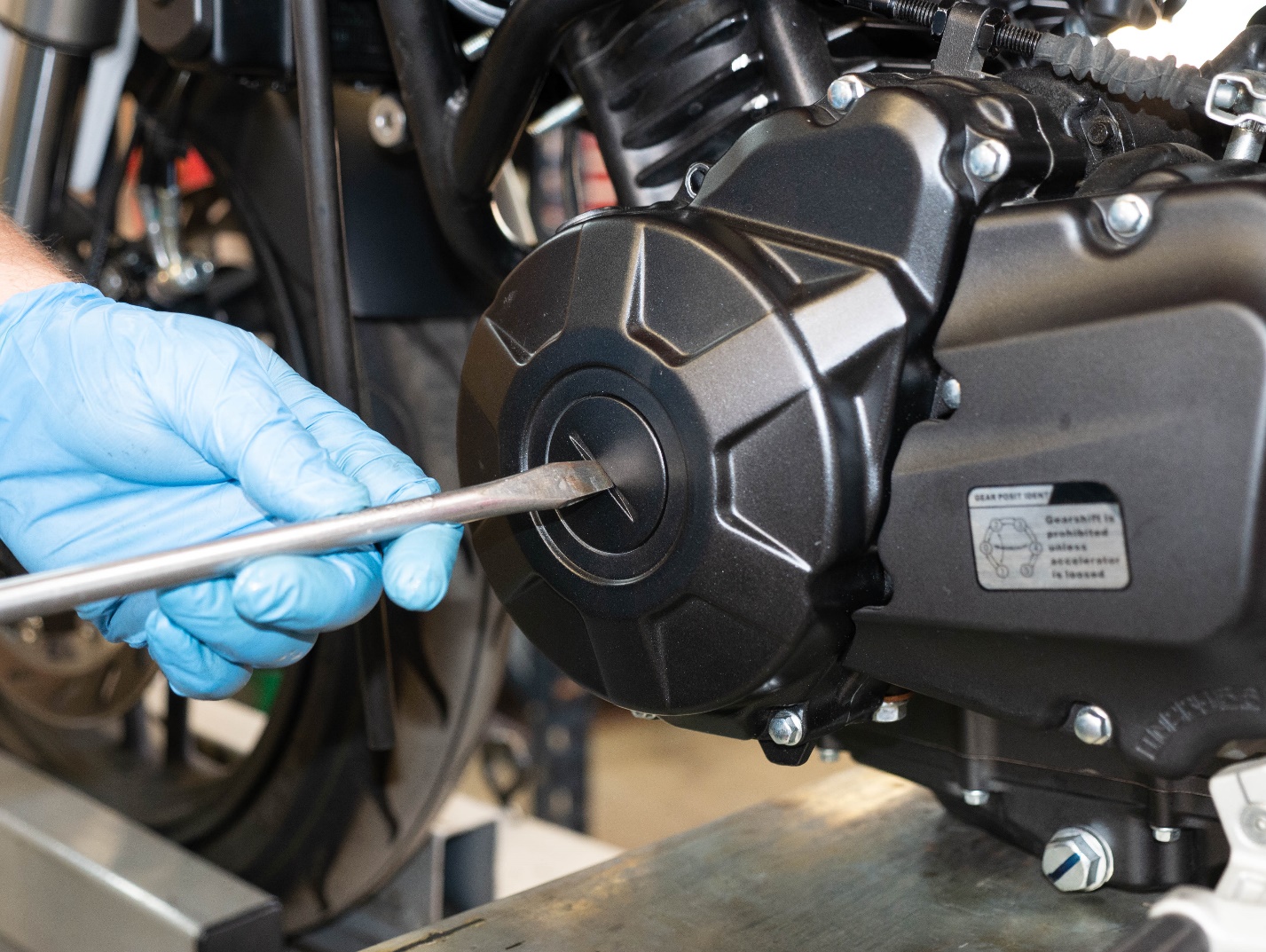
Remove the access port on the left side of the engine crankcase with a wide flathead screwdriver.
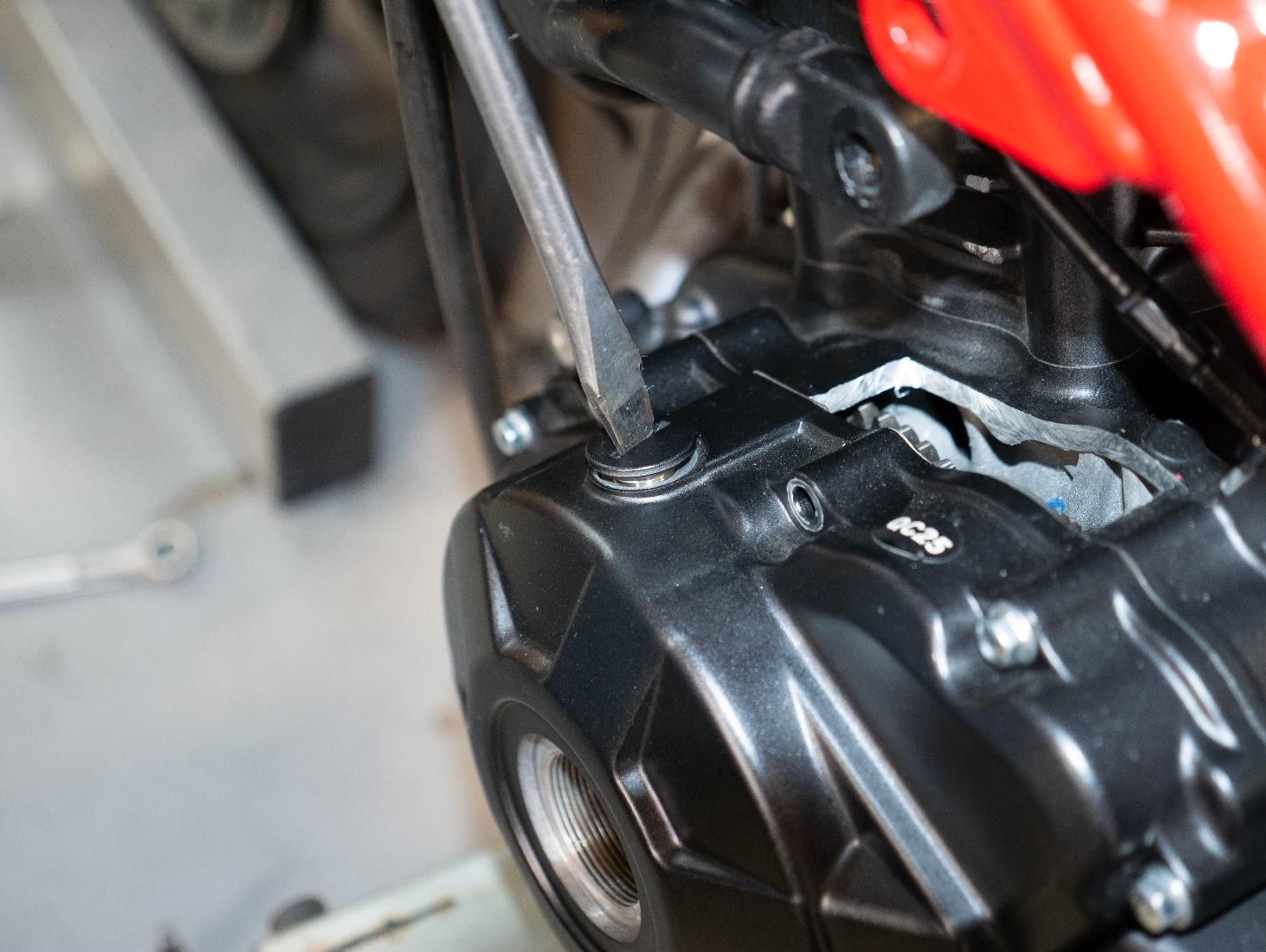
Remove the engine view port cover with a wide flathead screwdriver from the top left of the engine crankcase.

Call us at (800) 884-4173